
What are sensor interfaces?
Protocols like LoRaWAN and 5G dominate a lot of the discussion about the internet of things. Other topics include what kind of sensors you might need for a smart building, how IoT could make a project more efficient, and so on.
But there are a few more things to think about when it comes to choosing what to do and how to do it, especially sensor interfaces.
Despite not being the most glamorous component of an IoT network, they play a crucial role. Even if you have the most advanced minute accuracy sensing technology and the world’s fastest communication protocol, you can only go so far with the wrong sensor interface.
What is a sensor interface?
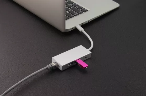
You are probably reading this on a device that has a USB port on it. Because it connects to so many devices and unifies communications in ways that would not otherwise be possible with proprietary interfaces, a USB is perhaps the most common example of a sensor interface in everyday life.
Comprehensively, in the web of things, a sensor connection point is a scaffold between a gadget and any joined sensor. The interface sends the data that the sensor has collected to the attached device, such as a radio transmitter or water level sensor.
The complexity of the various interface options varies. SDI-12, on the other hand, relies on microprocessors to streamline information, whereas an analog interface might transfer data using current regulation. We’ll go over a few common IoT sensor interfaces in this section.
I²C
I2C is a very common and common interface because it can connect many different devices to a single board and is relatively easy to integrate.
An interface for serial communications is known as I2C, which stands for Inter-Integrated Circuit. Rather than being referred to as “I2C,” which is incorrect, it ought to be referred to as “I-squared-C.” However, the fact that a 2 is so uncommon has naturally led to the I2C misnomer. I2C, which is made up of two standard wires that enable bidirectional communication, is the subject of all discussions. The Serial Data Line (SDA) is responsible for transmitting data, and the Serial Clock Line (SCL) is responsible for synchronizing data speeds.
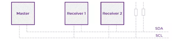
I2C can carry up to 1024 devices with 10 bit addressing and up to 128 devices with 7 bit addressing off of a single mainboard without becoming congested. An acknowledge/not-acknowledged pattern is followed by signals, with an acknowledgement signal of one bit for every eight bits of data in newer protocols.
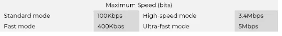
Although higher speeds are possible, I2C typically transfers data at speeds between 100Kpbs and 400Kpbs. I2C provides a highly adaptable method for interacting with both small and large end devices due to the fact that any device can be designated master or receiver.
Why pick an I²C interface?
Advantages
Supports multiple masters and receivers on the same circuit. Data packets can be as long as necessary. There are no arbitrary limits on the number of data frames. An efficient collision-resolution mechanism improves capacity. A wide variety of sensors and devices are available.
Disadvantages
Slower than some interfaces and only designed for device-to-device communication
SDI-12
Due to its inherent ability to preserve data in its rawest form, the Serial Data Interface at 1200 baud, or SDI-12, is prevalent in agricultural and environmental sensing equipment.
Through included microprocessors that carry out computations on the device side, SDI-12-capable sensors are able to achieve high data accuracy. Before transmitting the data, this permits individual sensors to carry out averaging and correction calculations.
SDI-12 may be utilized in low-power, low-data-rate systems for a number of reasons. The speed of 1200 bits per second, or 1200 baud, indicates that individual transmissions are quite small. By intelligently requesting specific sensors for their data, the central master module acts as a logger, indexing data from up to 62 devices simultaneously.
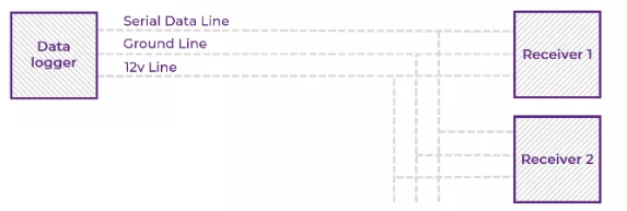
The SDI-12 bus is comprised of a serial data line for carrying signals, along with a ground line and 12v line for power delivery. The simple nature of SDI-12 allows for numerous connections off one master device with the added benefit of microprocessor data management.
For some more information on where you might find SDI-12, have a look at Delta-T’s page where it forms the backbone of their soil moisture sensors.
Why pick an SDI-12 interface?
Advantages
capable of communications over hundreds of meters Intelligent per-sensor indexing Sensor-side data processing with conversions Wiring is relatively straightforward in light of the background processing. The accuracy of the wired signal is maintained regardless of distance. Sensors can be swapped out of the system without reconfiguring the master logger.
Disadvantages
Slow data rate Managing a large SDI-12 system requires more expertise in setup and maintenance than other interfaces, making it less hands-off than other options.
UART
A serial integrated circuit is known as the Universal Asynchronous Receiver/Transmitter, or UART. UARTs take equal information communicated starting with one gadget then onto the next and convert it to sequential to make the exchange, changing over it back to resemble once the information has been sent across.
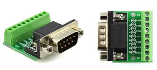
The RS232, RS422, and RS485 types of UART are the most prevalent. Although VGA actually utilized analog video with I2C for control messages, many interfaces using the RS specification resemble VGA connectors.
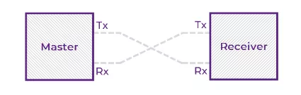
A UART interface only has two wires that connect the Tx pin to the Rx pin of another UART. The way data is sent by UART is what makes it asynchronous. UART uses the same baud rates as I2C and its start and stop bits because there is no internal clock to synchronize transfers between devices.
A data frame of five to nine bits, a parity bit, and then one to two stop bits are preceded by the start bit. The data frame, which is the main part of the packet, is identified to the receiver by a parity bit that basically checks the bits for errors. On the off chance that the quantity of “1” bits in the information outline amount to a much number, the equality ought to be 0, and assuming the quantity of 1s are odd, it ought to be odd. Anything else points to a mistake.

UARTs use a baud rate and the start and stop bits to control how data is sent rather than an internal clock. UARTs can still function with slightly mismatched baud rates between them, despite the fact that the clock in most digital systems requires complete synchronization between devices.
With twisted pairs of balanced signals, some protocols, like RS485 can communicate over very long distances even with a lot of external noise or interference. In multi-drop busses, where multiple devices wish to share the same physical medium, they are also suitable.
Why pick a UART interface?
Advantage
Simplicity: only two wires connect devices. This is a very popular interface for a lot of devices that are still in use today. No clock signal is needed. Different data rates for different applications and distances. Some versions, like RS485, can communicate over long distances.
Disadvantages
Asynchronous communications can result in mismatched baud rates due to exchange that is performed at the byte level and requires a higher protocol to define the meaning of the data.
Analogue
Due to their long history, analog sensor interfaces still make up the majority of connections worldwide.
Despite being older than SDI-12 and I2C, analog solutions are tried-and-true and simple to implement. Analogue signals are easy to incorporate into any system because most controllers will recognize them, despite the fact that they are not as specialized for certain tasks as more modern standards.
The method by which data are transmitted sets analog systems apart from others. Despite the fact that they certainly experience power spikes while transmitting, digital systems maintain a current that is more consistent than analogue ones. Analog systems transmit data directly between devices using electrical signals, allowing for greater variation in power consumption.
Analog voltage and analog current are two of the most prevalent types of analog signals.
Analogue voltage
Analog voltage systems are widely recognized and, as a result, widely supported on nearly every device, making sensor integration as simple as possible.
As a result, voltage-based interfacing works best when multiple devices that all need to run on the same physical network are used. 0-10 volts is a fairly common configuration for an analogue voltage integrated circuit.
Analogue current
Somewhat further developed than voltage interfaces, flow based flagging is more powerful against electrical impedance. The fact that the current serves as a natural indicator of potential component failure is one advantage of current-regulated circuits, even though specified currents can vary. Wyld uses an interface that runs between 4mA and 20mA. A line dropping to 0 immediately indicates a problem due to the 4mA operating current. Because the zero position of a voltage-regulated interface is the same as if there were no charges moving across it at all, it is unable to provide this level of insight.
Although current interfaces aren’t as common as voltage-based ones, they are still popular because they offer a more refined analog package.
Why pick an analogue interface?
Advantages
Simple physical connections and no complicated software to manage a wider range of data transfer speeds Easy to implement and very common
Disadvantages
Digital signals must be converted to analog before being transmitted. Versatile, but not optimized for very specific use cases. prone to electrical interference from nearby components
It doesn’t end here
The sensor interfaces discussed above only represent a portion of the options that are available. There is a lot of the internet of things, and not every option is right for the job.
Wyld are therefore not constrained in any way in their offerings. The skilled engineers who create low-power IoT modems frequently use a variety of interface technologies. If you do not find the interface option you are looking for on this page, just keep in mind that we will work with whatever the brief calls for.