
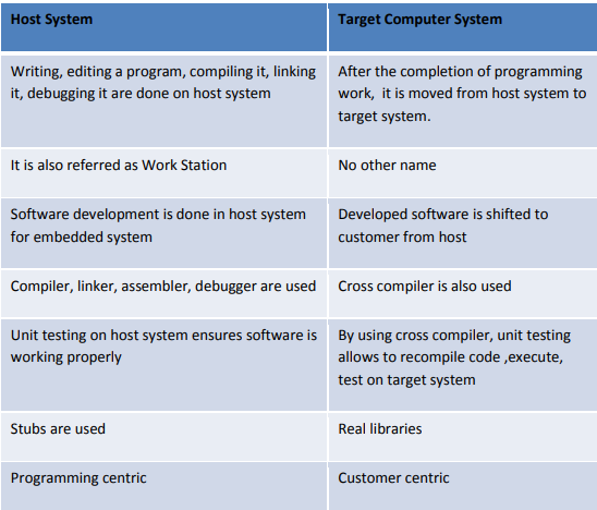
I. HOST AND TARGET MACHINES
• Host
a system that runs all of the programming tools. This is where embedded software is created, compiled, tested, debugged, and optimized before it is put into the target device.
Target
After writing the program, compiled, assembled and linked, it is moved to target
– After development, the code is cross-compiled, translated – cross-assembled, linked
into target processor instruction set and located into the target
Cross Compilers:
pilers:
• A cross compiler that sudden spikes in demand for have framework and produces the paired guidelines that is destined to be
grasped by your objective microchip.
• A compiler that can produce executable code for a platform other than the one on which it is currently running is known as a cross compiler. A cross compiler, for instance, generates code that runs on an Android smartphone while running on a Windows 7 PC.
• The compilers, assemblers, and linkers that are included in the majority of desktop systems that serve as hosts can run on the host. Native tools are the name of these tools.
• Assume a Windows NT system’s native compiler is based on an Intel Pentium processor. If the target microprocessor is also an Intel Pentium, this compiler may be possible. If the target microprocessor is not Intel, such as MOTOROLA, Zilog, or others, this is impossible.
• A cross compiler that sudden spikes in demand for have framework and produces the paired guidelines that is destined to be
grasped by your objective microchip. This cross compiler is a program that can perform the aforementioned function. If we write C/C++ source code that runs on the host and compiles with the native compiler, we can also run it on the target by compiling it with the cross compiler.
• Even though there is no issue with the if, switch, or loops statements for either compiler, that may not be possible in all cases. However, there may be an error regarding the following:
Data structures may differ between two machines; host and target sizes may differ in function declarations; and
Capacity to get to 16 and 32 cycle passages dwell at two machines.
Occasionally, a cross compiler may warn of an error that the native compiler may not.
Cross Assemblers and Tool Chains
If the target system is unable to run an assembler on its own, cross-assembling is required.
• A cross assembler is a host-based program that generates target-specific binary instructions. The cross assembler takes an assembly language file (.asm file) as its input and outputs a binary file.
• A cross-assembler is the same as any other assembler, except that it runs on a different CPU than the one it assembles code for.
Tool chain for building embedded software shown below
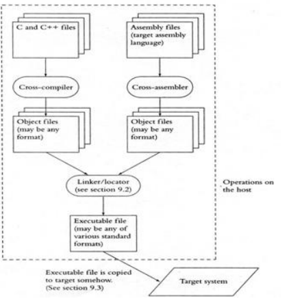
The process of developing software for an embedded system is depicted in the figure.
As depicted in the figure, the input files for the subsequent tool are the output files for the previous one. Because of this, the tools need to work together.
A tool chain is a collection of tools that are compatible in this way. Tool chains that build programs for different targets and run on different hosts.
II. LINKER/LOCATORS FOR EMBEDDED SOFTWARE
• Linker
– A computer program known as a linker or link editor combines multiple object files created by a compiler into a single executable, library, or other object file.
Locator
locate embedded binary code in the processors of the target • generate target machine code, which the locator affixes to the RTOS; the combined code, known as the map, is then copied into the ROM of the target
Linking Process shown below
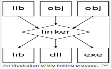
When a user requests to run a program, the native linker creates a file on the host system’s disk drive that is read by the loader, an operating system component.
• The program is copied from the disk into the memory by the loader, which then locates the memory into which it should be loaded.
• Address Resolution:
Native Tool Chain
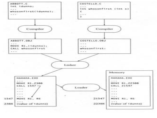
Explanation for above native tool chain figure
Above Figure shows the most common way of building application programming with local instruments. The fact that many microprocessor instructions include the addresses of their operands is one issue that the tool chain must address.
• Because the MOVE instruction in ABBOTT.C will load the value of the variable idunno into register R1, the variable’s address must be included in the figure above. In a similar vein, the whosonfirst’s address must be included in the CALL instruction. Address resolution is the method of problem solving.
• When compiling the abbott.c file, the compiler does not know what the addresses of whosonfirst() and idunno are; instead, it separates them and leaves them as object files for the linker.
• At this point, the linker will determine that the address of idunno must be patched to instructoin’s whosonfirst() call.
When linker puts the two article records together, it sorts out idunno and whosonfirst() are in connection
for execution and spots in executable records.
• The loader knows precisely where idunno and whosonfirst() are in memory after copying the program into memory. The entire procedure is referred to as address resolution.
Output File Formats
In most implanted frameworks there is no loader, when the finder is done then result will be duplicated
to target.
As a result, the locator must be aware of the program’s location and restore all memories.
You can tell locaters where the program will be on the target system thanks to a mechanism.
Finders utilize quite a few different result record designs.
Any file format that your locator produces must be supported by the tools you use to load your program into the target.
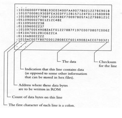
- intel Hex file format
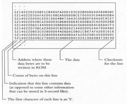
- Motorola S-Record format
Intel Hex file format:
below figure shows Intel Hex file format
Motorola S-Record format
Loading program components properly:
In the embedded environment, locators must also resolve the requirement that some parts of the program end up in RAM and others in ROM.
For instance, remember that whosonfirst() ends up in ROM even when power is off. Because the data in the variable idunno can be altered, it would need to be in RAM.
Application programming does not have this problem because the loader copies the entire program into RAM.
The majority of tools chains solve this issue by segmenting the programs. The locator is able to store each segment alone in memory because it is a piece of program.
With the help of segments, embedded system programmers can ensure where the first instruction is at a specific location when the processor powers on.
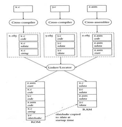
Figure shows how a tool chain might work in a system in hypothetical system that contains three
modules X.c, Y.c and Z.asm.The code X.c contains some instructions, some uninitialized data and
some constant strings. The Y. c contains some instructions, some uninitialized and some initialized
data. The Z.asm contains some assembly language function, start up code and uninitialized code
.The cross compiler will divide X.c into 3 segments in the object file
First segment: code
Second segment: udata
Third segment: constant strings
The cross compiler will divide Y.c into 3 segments in the object file
First segment: code
Second segment: udata
Third segment: idata
The cross compiler Z.asm divides the segments into
First Segment: assembly language functions
Second Segment: start up code
Third Segment t: udata
The linker/Finder reshuffle these portions and places Z.asm fire up code at where processor
starts its execution, it places code portion in ROM and information fragment in Slam. The module is typically automatically divided into two or more segments by most compilers: Initialized, constant strings, uninitialized code, and the instructions (code). You can also specify the segment or segments into which the assembler’s output should be placed with cross assemblers. The segments are stored in memory by Locator. One commercial locator is instructed on how to construct the program in the two lines of instructions that follow.

A list of segments is indicated by the –Z at the beginning of each line. The address where the segment should go is at the end of each line.
Starting at the given address, the segments are sequentially stored in memory by the locator.
The segments CSTART, IVECS, and CODE must be positioned sequentially at address 0.
The addresses of the segments IDATA, UDATA, and CTACK are 8000.
Some other features of locators are:
The locator will notify you if a program does not fit within the RAM or ROM address ranges that we can specify.
It will place the segment below that address, which is useful for stack memory, if we specify the address at which the segment is to end.
We can group each segment, tell the locator where the group is going, and then deal with each segment individually.
Initialized data and constant strings:
Let us see the following code about initialized data:
define FREQ 200
Static int ifreq= FREQ;
void setfreq(int freq)
{
int ifreq;
ifreq = freq;
}
where the ifreq variable needs to be kept. In the preceding code, the initial value of ifreq must be stored in ROM because this is the only memory that stores data when the power is off. In the second case, the initial value of ifreq must be stored in RAM due to the frequent changes made by setfreq ().
The only solution to the issue is to copy the initial value into the variable at startup while simultaneously storing the variable in RAM and ROM. Loader sees that each introduced variable has the right introductory
esteem when it stacks the program. However, because the embedded system lacks a loader, the application itself must arrange for the copying of initial values into variables.
In order to address this issue, the locator creates a shadow segment in the read-only memory (ROM) that contains all of the initial values and copies that segment to the actual initialized data segment upon startup. The RAM’s contents are garbage when an embedded system is powdered. They only become all zeros if some embedded system start-up code sets them to zero.
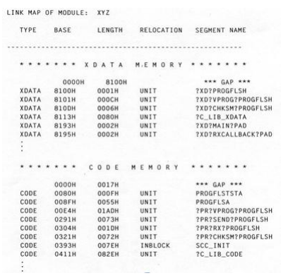
Locator Maps:
Most locators will create an output file, called map, that lists where the locator placed each
of the segments in memory.
• A map consists of address of all public functions and global variables.
• These are useful for debugging an ‘advanced’ locator is capable of running a startup code in
ROM, which load the embedded code from ROM into RAM to execute quickly since RAM is
faster
Locator MAP IS SHOWN BELOW:
RAM is quicker than ROM and flash, among other types of memory. If the program is stored in RAM rather than ROM, the rapid instruction set computer (RISC) can execute it quickly. However, when the system starts up, they copy the programs to RAM and store them there.
Slowly, the start-up code is executed directly from ROM. The remaining code is copied to RAM for quick processing. Before being stored in the ROM, the code is compressed, and when it is copied to RAM, the start-up code is decompressed.
The locator will perform all of these tasks for the system; the locator must develop a program that can be stored in ROM and executed in RAM.
Getting embedded software into the target system:
• The locator will build a file as an image for the target software. There are few ways to
getting the embedded software file into target system.
– PROM programmers
– ROM emulators
– In circuit emulators
– Flash
– Monitors
PROM Programmers:
The traditional approach involves creating a file in ROM or PROM to transfer software from the locator output file to the target system.
Since making ROMs costs a lot of money, it’s best to do so after software development is finished. A PROM programmer device is needed to load the program into PROM.
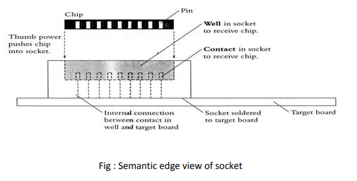
If you intend to modify and debug the software, PROM is a good choice if the software is small enough. Place the PROM in the Target’s socket before soldering it directly into the circuit (as shown in the figure below). If the PROM contains software with the bug, you can remove it from the target and place it in the eraser or waste basket when we find a bug. In any case program another PROM with programming
which is bug fixed and free, and put that PROM in the attachment. To remove PROM from the socket, we require the inexpensive chip puller, a small instrument. The PROM can be inserted into the socket using only our thumb (see figure 8). We are responsible for making the PROM programmer and the locator compatible if they come from different manufacturers.
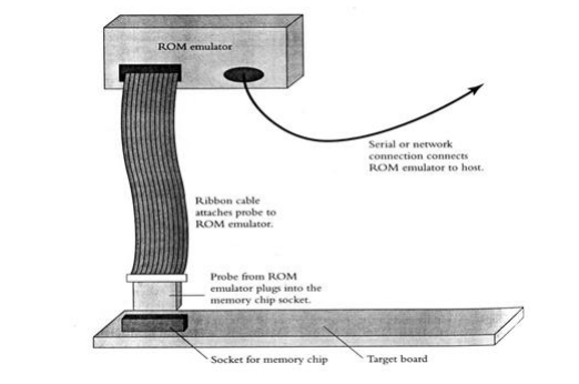
ROM Emulators:
A ROM emulator is an additional method for installing software on the target. A device that inserts the ROM into the target system is known as a ROM emulator. Figure 9 shows that it just looks like ROM; The ROM emulator is a large electronic box with a serial port or a network connection for connecting to your host. The ROM emulator can receive files created by the locator through software running on your host. Make sure the file format created by the locator is understood by the ROM emulator.
In circuit emulators:
To investigate the product, then we can utilize overlay memory which is a typical element of
in-circuit emulators. In-circuit emulator is a component to get programming into focus for troubleshooting
purposes.
Flash:
If your target stores its program in flash memory, one option is to place the flash memory in a socket and treat it like an EPROM. On the other hand, if your target has a serial port, a network connection, or some other way to communicate with the outside world, link, then your target can communicate with the outside world, and flash memories give you another option: You can create software that uses the communication link to receive new programs from your host and write them to the flash memory. Despite the fact that this may seem difficult,
The reasons behind the host’s new programs:
For debugging, you can load new software into your system without removing the chip and replacing it.
The process of downloading new software is quicker than taking the device out of its socket, programming it, and then putting it back in.
If customers wish to install new software versions on your product.
This method has some drawbacks, including:
Here chip can’t bring the directions from streak.
The software for flash programming must copy itself into the RAM, and the locator must oversee how those flash memory instructions are carried out.
We need to devise a foolproof method for the system to install the flash programming software on the target, which means that the target system needs to be able to download the file correctly even if the previous download fails in the middle.
We must modify the flash programming software in RAM before copying it to flash.
Monitors:
It is a program that can load new programs onto the system and is located in the target ROM. You can send data across a serial port with a typical monitor, store software in the target RAM, and then run it. A few debugging services, such as setting break points, display memory, and register values, are provided by monitors, which occasionally also serve as locators. You can develop your own monitor application.
DEBUGGING TECHNIQUES
I. Testing on host machine
II. using laboratory tools
III. an example system
Introduction:
The code that the developer creates for the embedded system software will have numerous bugs. There is a possibility that the testing and quality assurance procedures will lessen the number of bugs. However, writing software with a few fewer bugs is the only way to ship the product with fewer bugs. The world very prejudiced of buggy implanted frameworks. The embedded system software development process will rely heavily on testing and debugging.
Testing on host machine :
• Goals of Testing process are
– Find bugs early in the development process
– Exercise all of the code
– Develop repeatable , reusable tests
– Leave an audit trail of test results
Early on in the development process, locate the flaws:
This sets aside time and cash. Early testing lets you know how many bugs there are and how much trouble you’re having.
BUT: The hardware may be unstable and faulty because hardware engineers are still working on it, or the target system may be available early in the process.
Exercise all of the code:
Even though we hope they will never occur, exercise all exceptional cases to gain experience with how things work.
BUT: Practicing all the code in the target is unimaginable. For instance, a laser printer might have code to deal with a situation in which the user presses one of the buttons just as a paper jam occurs, but this code would have to be tested in real time in this scenario. We must cause the paper to jam and then press the button in a millisecond; this is difficult to accomplish.
Develop reusable, repeatable tests:
Finding the bug after seeing it once but not finding it frustrates. We require repeatable tests in order to prevent refuse from occurring again.
BUT: In the target environment, it is difficult to create repeatable tests.
Example: The bug in the bar code scanner will make it difficult to locate and address because it will display the previous scan results each time it is scanned.
Leave an “Audit trail” of test result:
Similar to how the telegraph “seems to work” in a network environment, what it sends and receives is difficult to understand but important for storing.
BUT: Because embedded systems do not have a disk drive, it is difficult to always keep track of the results we obtained.
Conclusion: It is difficult to achieve the objectives by testing software on the target system, so avoid doing so. The option is to test your code on the host framework.
Basic Testing Method:
The fundamental procedure for testing embedded software on the development host is depicted in the figure that follows. The target system is depicted on the left side of the figure, while the host will be tested on the right. Both sides of the figure’s hardware-independent code are compiled from the same source.
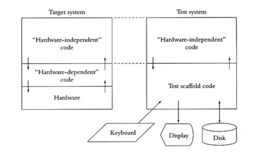
On the right side, test scaffold software has taken the place of hardware-dependent and hardware-dependent code. On the target system, the scaffold software calls the same functions as the hardware independent code and provides the same entry points as the hardware dependent code. The scaffold software receives its instructions from a file or the keyboard; It generates output for the display or log file.
Conclusion: You can create a clean interface between the rest of the code and hardware-independent software using this method.
Calling Interrupt Routines by scaffold code:
Tasks will be carried out in response to interruptions. Therefore, the test scaffold must carry out the interrupt routines in order to cause the system to perform any action in the test environment. There are two parts to interrupts: one that deals with hardware (via hardware-dependent interrupt calls) and the other with the rest of the system.
Calling the timer interrupt routine:
One interrupt routine your test scaffold should call is the timer interrupt routine. In most embedded
systems initiated the passage of time and timer interrupt at least for some of the activity. You could
have the passage of time in your host system call the timer interrupt routine automatically. So time
goes by your test system without the test scaffold software participation. It causes your test scaffold
to lose control of the timer interrupt routine. So your test scaffold must call Timer interrupt routine
directly
Script files and Output files:
a test scaffold that calls the various interrupt routines with particular data and in a particular order. a test scaffold that, after reading a script from a file or from the keyboard, makes calls in accordance with the script. Although the script file need not be a project, it should be simple.
Example: script file for bar code scanner testing
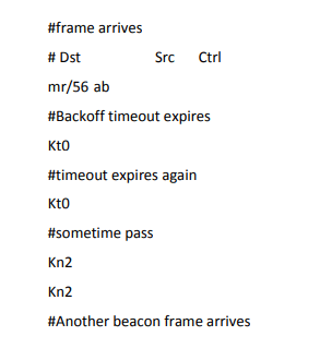
Each command in this script file causes the test scaffold to call one of the interrupts in the hardware
independent part.
The test scaffold calls one of the timer interrupt routines in response to the kt0 command. The test scaffold calls a different timer interrupt routine the indicated number of times in response to the command kn followed by a number. The test scaffold writes the data into memory in response to the command mr.
Features of script files:
We could write the parser more quickly because the commands are only two or three letters long.
Remarks are permitted, remarks script document show what is being tried, demonstrate what results
you expect, and gives adaptation control data and so forth.
Data can be entered in either Hexadecimal or ASCII.
Most advanced Techniques:
These are few additional techniques for testing on the host. It is useful to have the test scaffold
software do something automatically. For example, when the hardware independent code for the
underground tank monitoring system sends a line of data to the printer, the test scaffold software
must capture the line, and it must call the printer interrupt routine to tell the hardware independent
code that the printer is ready for the next line.
There may be a need that test scaffold a switch control because there may be button interrupt
routine, so that the test scaffold must be able to delay printer interrupt routine. There may be low,
medium, high priority hardware independent requests, then scaffold switches as they appear.
Some Numerical examples of test scaffold software: In Cordless bar code scanner, when H/W
independent code sends a frame the scaffold S/W calls the interrupt routine to indicate that the
frame has been sent. When H/W independent code sets the timer, then test scaffold code call the
timer interrupt after some period. The scaffold software acts as communication medium, which
contains multiple instances of H/W independent code with respect to multiple systems in the
project.