


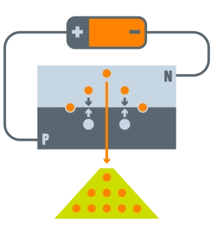
A semiconductor device known as a Light Emitting Diode (LED) is capable of producing light when an electric current flows through it. Light is produced when electrons from n-type semiconductors and holes from p-type semiconductors recombine. The semiconductor material’s bandgap determines the emitted light’s wavelength. Bandgaps are typically wider in harder materials that have stronger molecular bonds. Semiconductors made of aluminum nitride are referred to as ultra-wide bandgap semiconductors.
Since the beginning of written history, humankind has sought to control light. We are all affected by a biological sensation by the power of illumination. We’ve moved on from the more volatile gasoline vapor to the chemical combustion of wood-based energy. Metal coils that were warm, glowing, and delicate took the place of the actual flame. The humble electron’s ability to release energy through electroluminescence is my favorite form of light. LEDs, or light emitting diodes, offer nearly limitless options for combating darkness and are significantly more energy efficient than previous methods.
Simple ON/OFF with GPIO
A simple flashlight can be made by simply connecting LED pins to a coin cell and adding some tape. What about the pizzazz and control? Even though LEDs only permit current to flow in one direction, this does not mean that you can only go in that direction. We’ll put together a few basic parts and test out what microcontrollers can do for our lighting requirements.
First, let’s talk about GPIOs. These are simple input and output General Purpose Input and Outputs. This implies that relying upon how we set it up, that pin will get a voltage sign or put out a voltage signal. Our “On” (or output) voltage on the RedBoard is a very useful 5 volts. By writing digitalWrite(PIN_NUMBER, HIGH), we force the ATMEGA IC to perform this action; in the Arduino program. However, if you simply paste that into the loop section, you’ll find that doesn’t really work. We are required to declare the pin’s design. Therefore, we create a variable for quick access to our pin number: PIN_NUMBER. We’ll use the default pin 13 on the RedBoard Qwiic for simplicity’s sake. Then, we need to write pinMode(PIN_NUMBER, OUTPUT); in the setup() function. This indicates that our integrated circuit is utilizing that pin as an output. The IC therefore knows precisely what to do when we write that digital high. That pin would be at 5V relative to GND (0V) if you connected an oscilloscope or multimeter to it until you set it to LOW using digitalWrite(PIN_NUMBER, LOW); That basically amounts to a blink from off to on and then back to off. Time delays can be added for various effects.
//A delay is used in this example to turn a GPIO pin ON and OFF.
PIN_NUMBER; const int //Use the built-in LED on pin 13 on the RedBoard Qwiic by replacing “PIN_NUMBER” with a physical pin. Void setup() pinMode(PIN_NUMBER, OUTPUT); //set the digital pin as the output using digitalWrite(PIN_NUMBER, HIGH) and void loop() //After a 5000-second delay, the LED connected to pin 13 turns on. //delay(Milliseconds), so “5000” corresponds to five seconds of digitalWrite(PIN_NUMBER, LOW); //Driven associated with pin 13 goes OFF
delay(5000); //delay(Milliseconds), so “5000” corresponds to 5 seconds
“Ok, What Does this Mean for Me?”
This shows that these “auxillary pins” can be used for either input or output, as in our case. After we complete this step, there are numerous options. We are going to look at some fun arrangements, effects, and practical applications for LEDs from this point forward.
I might be stressing the microcontroller’s pins too much. They warrant their own huge number of instructional exercises, yet haven’t arrived for those. They will serve as the web of control for our numerous LEDs, so I’m pushing them.
The higher perspective is that at some spot in our circuit, there is a place of voltage. We are able to illuminate our LED if the voltage at this point is high enough—but not too high—so that we do not blow the LED. The power we require comes from a GPIO pin’s output. In a room full of switches and bulbs, they could be compared to fancy switches.
Lights, Camera, ACTION
Blink like Booyah
Check out the circuit diagram below to see how everything is connected.
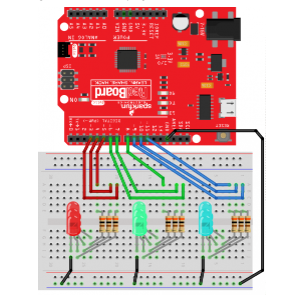
I was free to have a little fun with this one. Each LED set is being turned on one at a time. Before moving on to the next set, we will turn them off one at a time once the set is turned on.
The following code should be copied and pasted into the Arduino IDE. Try it out by hitting the upload button!
//In this example, each LED set is turned on one at a time. Before moving on to the next set, we will turn them off one at a time once the set is turned on.
//Declare that the number of pins is 8;
green_b const int = 7;
const int GREEN_C equals six;
const int RED_A equals 5
const int RED_B is four;
const int RED_C is three;
const int BLUE_A equals 11
const int BLUE_B equals ten;
const BLUE_C = 9 in int
turn_time const = 300; //Experiment with this integer!
void setup() // Set output pinMode(GREEN_A, OUTPUT) to initialize the pins;
pinMode(GREEN_B, Result);
pinMode(OUTPUT, GREEN_C);
pinMode(OUTPUT, RED_A);
pinMode(OUTPUT, RED_B);
pinMode(OUTPUT, RED_C);
pinMode(OUTPUT, BLUE_A);
pinMode(OUTPUT, BLUE_B);
pinMode(OUTPUT, BLUE_C);
//These sequences simply turn on three of the same color one by one using void loop(). After that, turn them off one at a time.
digitalWrite(HIGH, BLUE_A); // delay(turn_time) to turn on the LED (HIGH is the voltage level); // perform a second digitalWrite(BLUE_B, HIGH) after waiting; // delay(turn_time) to turn on the LED (HIGH is the voltage level); // perform a second digitalWrite(BLUE_C, HIGH) after waiting; // delay(turn_time) to turn on the LED (HIGH is the voltage level); // sit tight briefly
digitalWrite(BLUE_A, LOW); // Make the voltage low enough to turn off the LED by setting delay(turn_time); // perform a second digitalWrite(BLUE_B, LOW) after waiting; // Make the voltage low enough to turn off the LED by setting delay(turn_time); // perform a second digitalWrite(BLUE_C, LOW) after waiting; // Make the voltage low enough to turn off the LED by setting delay(turn_time); // delay digitalWrite(GREEN_A, HIGH) for a second; // delay(turn_time) to turn on the LED (HIGH is the voltage level); // delay digitalWrite(GREEN_B, HIGH) for a second; // delay(turn_time) to turn on the LED (HIGH is the voltage level); // delay digitalWrite(GREEN_C, HIGH) for a second; // delay(turn_time) to turn on the LED (HIGH is the voltage level); // wait a second for digitalWrite(LOW, GREEN_A); // delay(turn_time) to turn off the LED (HIGH is the voltage level); // hang tight briefly
digitalWrite(GREEN_B, LOW); // switch the Begun (HIGH is the voltage level)
delay(turn_time); // wait a second for digitalWrite(LOW, GREEN_C); // delay(turn_time) to turn off the LED (HIGH is the voltage level); // perform a second digitalWrite(RED_A, HIGH) after waiting; // delay(turn_time) to turn on the LED (HIGH is the voltage level); // perform a second digitalWrite(RED_B, HIGH) after waiting; // delay(turn_time) to turn on the LED (HIGH is the voltage level); // hang tight briefly
digitalWrite(RED_C, HIGH); // delay(turn_time) to turn on the LED (HIGH is the voltage level); // delay digitalWrite(RED_A, LOW) for a second; // switch the Begun by making the voltage LOW
delay(turn_time); // perform a second digitalWrite(RED_B, LOW) after waiting; // Make the voltage low enough to turn off the LED by setting delay(turn_time); // delay digitalWrite(RED_C, LOW) for a second; // Make the voltage low enough to turn off the LED by setting delay(turn_time); // please hold on a second.