


The BE junction is biased forward, while the CB junction is biased in the opposite direction, as shown in the figure of an n-p-n transistor (see transistor biasing). In comparison to the CB junction, the BE junction’s depletion region has a narrow width.
The electrons flow from the emitter to the base as a result of the forward bias at the BE junction, which lowers the barrier potential. Because the base is thin and lightly doped, it has few holes. As a result, about 2% of the electrons from the emitter recombine with the holes in the base region and flow out of the base terminal.
This comprises the base current, it streams because of recombination of electrons and openings (Note that the bearing of traditional current stream is inverse to that of the progression of electrons). The collector current will be formed when a significant number of the remaining electrons cross the reverse-biased collector junction. Thus, according to KCL, the base current is extremely small in comparison to the collector and emitter currents.
Electrons make up the majority of charge carriers in this case. The only difference between a p-n-p and a n-p-n transistor is that the majority of charge carriers are holes rather than electrons. In a BJT, minority charge carriers account for the majority of current flow, while majority carriers account for only a small portion. As a result, they are referred to as minor carrier devices.
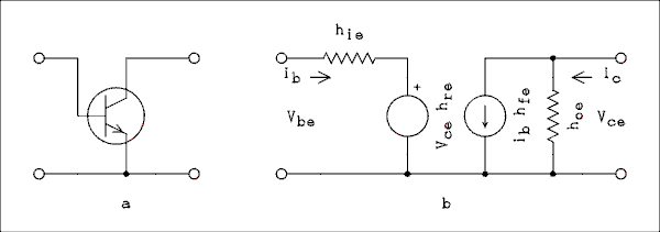
A diode is used to represent a p-n junction in an equivalent circuit to the BJT. A transistor is equivalent to two back-to-back diodes because it has two p-n junctions. This is called as the two diode similarity of the BJT.
Characteristics of Bipolar Junction Transistors A BJT consists of a collector, an emitter, and a base. Before we can discuss the characteristics of a bipolar junction transistor, we need to understand its modes of operation. The modes are Common Base (CB), Common Emitter (CE), and Common Collector (CC). Biasing of bjt Now that we’ve covered the modes, let’s talk about the characteristics of BJT. There are distinct characteristics for each mode of operation. The graphical representations of the relationships between the transistor’s various current and voltage variables constitute its characteristics. For various modes and parameters, p-n-p transistor characteristics are listed.
Common Base Characteristics Input Characteristics The p-n-p transistor’s input current and voltage are the collector base voltage (VCB) and the emitter current (IE).
The IE Vs VEB graph of a p-n-p transistor is comparable to the forward characteristics of a p-n diode due to the emitter-base junction’s forward bias. When VCB rises, fixed VEB experiences an increase in IE.
Yield Attributes
The result attributes show the connection between the result voltage and result current IC is the result current and gatherer base voltage and the producer current IE is the information current and fills in as the boundaries. In CB mode, the output characteristics of a p-n-p transistor are depicted in the image below.
We are aware that p-n-p transistors have positive IE and VEB and negative IC, IB, and VCB characteristics. The active region, the saturation region, and the cut off region are the three curve regions. The transistor operates normally in the area known as the active region.
This emitter junction is biased in the opposite direction. Now, both emitter-collector junctions are forward biased in the saturation region. Finally, the emitter and collector junctions are both reverse biased in the cut off region.
Characteristics of the Common Emitter The Common Emitter mode’s input characteristics are IB (Base Current) and VBE (Base – Emitter Voltage). As a result, the relationship between IB and VBE with VCE as a parameter will serve as the input characteristics for CE mode. The typical CE input characteristics are comparable to those of a forward-biased p-n diode and are depicted below for your reference. However, the base width narrows as VCB grows.
When the base current IB is the parameter, the output characteristics for CE mode are represented by the curve or graph that exists between the collector current (IC) and the collector-emitter voltage (VCE). The characteristics are depicted in the figure below.
Similar to the output characteristics of a common-base transistor, the p-n-p transistor has three regions: the active region, the cut-off regions, and the saturation region in CE mode. The emitter junction is biased in the opposite direction from the collector region in the active region.
In the cut-off region, the collector current is not completely cut off and the emitter junction is slightly reverse biased. Finally, the collector and emitter junctions are both forward biased in the saturation region.