


Content
- The Principle of DC Motors
- Types of DC Motors
- Construction of DC Machines
- Working of DC Motor
- Significance of back emf
- Voltage, Current, and Power Equations
- Advantages and disadvantages of a d.c. motor
Symbolic representation

The Principle of the DC Motor
- A DC motor is, first and foremost, a machine that converts DC power into mechanical power.
- Its operation is based on the principle that a current-carrying conductor experiences a mechanical force when immersed in a magnetic field.
- Fleming’s left-hand rule is used to specify the forces, and the magnitude is given by;
F = B*I*L*Sin (angel)
Where
F = Force
B = Magnetic flux density (Strength of Magnetic Field)
I = Current passing through the conductor
L = Length of the conductor
= Angle that the conductor makes with the magnetic field
types of DC motor:
DC motors, like generators, are classified into three categories based on the connections of the field winding to the armature:
- Shunt-wound motor
- A series-wound motor
- Compound-wound motor
- Short-shunt connection
- The long shunt connection
D.C. Shunt-wound motor

Fig. 1: D.C. Shunt-wound motor
The field winding is connected in parallel with the armature as shown in the above figure.
Characteristics of the D.C. Shunt Motors
- Fig. 1 shows the connection of the d.c. shunt motor.

Fig. 2: Ta/Ia characteristic
- The field winding is directly connected to the supply voltage V, which is assumed to be constant, so the field current Ish remains constant.
Ish = E/Rsh, remains constant.
- Hence, the flux in a shunt motor is approximately constant.
- And the armature current, Ia, is given as
Armature current = (shunt current + line current).
Ia = (Ish + iL).
Ta/Ia Characteristics
We know that in a direct-current (d.c.) motor,
Armature torque is directly proportional to flux and armature current.
Ta Flux *Ia
Because the motor is powered by a constant supply voltage, the flux is constant.
Armature torque is directly proportional to armature current.
Ta Ia
As a result, as shown in Fig.2, the Ta/Ia characteristic is a straight line passing through the origin. The shaft torque (Tsh), which is less than Ta, is represented by a dotted line. The curve clearly demonstrates that a high current is required to start a heavy load. As a result, starting a shunt motor under a heavy load is not preferred.
N/Ia Characteristics
The speed N of a motor is given by
Speed is directly proportional to flux and back e.m.f. Eb.
N Eb/Flux
Under normal conditions, the flux and back e.m.f.Eb in a shunt motor are nearly constant. As a result, as the armature current varies, the speed of a shunt motor remains constant, i.e. (dotted line AB in Fig. 3). It is clear that as the load increases, Eb = V-(Ia*Ra) and flux decreases due to armature resistance drop and armature reaction. It means that the motor’s speed decreases slightly with a load (line AC).

Fig. 3: N/Ia characteristic
N/Ta Characteristics

Fig. 4: N/Ta characteristic
In fig. 4, it shows the speed VS armature torque characteristic.
The above characteristics show that as the load torque increases, the speed decreases.
Conclusions
The following important conclusions are drawn by seeing the above characteristics:
- The speed of a shunt motor changes slightly from no-load to full load. As a result, it’s essentially a constant-speed motor.
- Because of Ta directly proportional to Ia, the starting torque is low.
D.C. Series-wound motor

Fig. 1: D.C. series-wound motor
The current flowing through the field winding in a d.c. series motor is the same as the current flowing through the armature. When the mechanical load on the motor increases, so does the armature current. As a result, as the armature current increases, so does the flux in the series motor, and vice versa.
Characteristics of the D.C. Series Motors
Ta/Ia Characteristics
We know that:
Ta ∝ Ia
Up to magnetic saturation flux ∝ Ia so that Ta ∝ Ia2
After magnetic saturation, flux is constant so that Ta ∝ Ia.

Fig. 2: Ta/Ia characteristic
- Thus, up to magnetic saturation, armature torque is directly proportional to the square of the armature current. Ta is increased by four times when Ta is doubled.
- As a result, the Ta/Ia curve is a parabola up to magnetic saturation (portion OA of the curve in Fig. 2).
- After magnetic saturation, however, torque is directly proportional to armature current.
- As a result, the Ta/Ia curve following magnetic saturation is a straight line (portion AB of the curve).
- This means that the starting torque of a d.c. series motor will be greater as compared to a shunt motor.
N/Ia Characteristics

Fig. 3: N/Ia characteristic

- The speed N of a series motor is given by:
N = Eb/flux where Eb = V-Ia (Ra + Rse)
- When the armature current increases, the back e.m.f.Eb decreases because Ia (Ra + Rse) decreases.
- Under normal circumstances, the drop is so small that it can be neglected.
N 1/flux
N 1/Ia up to magnetic saturation
- As a result, until magnetic saturation, the N/Ia curve follows the hyperbolic path depicted in fig. 3.
- After saturation, the flux and speed become constant.
N/Ta Characteristics

Fig. 4: N/Ta characteristic
- It is clear that a series motor develops high torque at low speed and vice-versa.
- It is because an increase in torque requires an increase in armature current, which is also the field current. The result is that flux is strengthened, and hence the speed drops (N 1/flux).
- The reverse happens should the torque be low.
D.C. Compound-wound motor
- A compound motor has both a series and a shunt field. The shunt field outperforms the series field every time. Compound motors are categorized into two types according to how the windings are connected.
- Cumulative-compound motors that have a series field assist the shunt field.
- Differential-compound motors in which the series field opposes the series field to a shunt field

Fig. 5: D.C. Compound motor
Characteristics of Cumulative-compound Motors
Ta/Ia Characteristics


Fig. 6: Ta/Ia characteristics
- The series field strengthens as the load increases, but the shunt field strength remains constant. As a result, total flux and thus armature torque (Ta Ia) increase.
- Due to the series field, the torque of a cumulative-compound motor is greater than that of a shunt motor for a given armature current.
N/Ia Characteristics

Fig. 7: N/Ia characteristic
- We know that as the load increases, so does the flux per pole. Consequently, the speed (N 1/) of the motor decreases as the load increases.
- We can see from the above characteristics that, as the load is added, the increased amount of flux causes the speed to decrease more than the speed of the shunt motor.
N/Ta Characteristics

Fig. 8: N/Ta characteristic
- The torque of a cumulative compound motor is greater than that of a shunt motor but less than that of a series motor for a given armature current.
Conclusions
- The presence of a shunt field prevents the motor from running away at no load.
- The presence of a series field increases the starting torque.
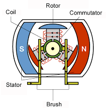
CONSTRUCTION
A DC motor is made up of the following components:
Yoke:
It is the outer part of the DC motor that supports the field poles, serves as a cover, and serves as the path for pole flox.
Field Poles:
It is made up of field windings, a pole core, and a pole shoe. To reduce eddy current, the pole core and shoe are laminated. The pole core is used to support the field winding, the pole shoe is used to evenly distribute the flux, and the field winding generates the North and South poles using the current passing through it.
Armature:
It is a component of the machine’s rotating element. It is made up of a core and an armature winding. The armature winding is housed in this core. To generate electromagnetism, armature windings form a coil.
Commutator
The armature coils of the DC machine induce an alternating e.m.f., and commutators are used to provide direct current to the armature. Commutators are made of copper and are separated from one another by mica sheets. Each commutator segment is connected by armature coils.
Brushes:
Brushes are made of carbon or electro graphite, both of which conduct electricity. They deliver a direct current supply from an external source to the commutator. The main disadvantage of DC motors is that they can produce spark as they rub against the commutator.

Fig. 10: Construction of d.c. motor

Fig. 10: Multipolar D.C. motor

WORKING OF DC MOTOR
- Consider the following multipolar d.c. motor section: When the terminals of the motor are connected to an external d.c. supply source.
- The field magnets are excited, resulting in the formation of alternate N and S poles.
- The armature conductors, as shown in fig. 9, carry currents out of the plane of the paper, whereas those under the s-pole carry currents in the plane of the paper. Because each armature conductor is carrying current and is placed in a magnetic field, a mechanical force acts on it.
- Using Fleming’s left-hand rule, it is obvious that the force on each conductor causes the armature to rotate anticlockwise. All of these forces combine to produce a driving torque, which governs the armature’s rotation.
- When a conductor moves from one side of a brush to the other, the current reverses and is influenced by the next pole, which has the opposite polarity. As a result, the force acting on the conductor is constant.
Back or Counter, E.M.F.
When the armature of a direct current motor rotates under the influence of the driving torque, the armature conductor moves through the magnetic field, causing e.m.f. to be induced in them as in a generator. Back e.m.f. Eb. is the induced e.m.f. that acts in the opposite direction to the applied voltage V (“Lenz’s Law”).
The back e.m.f. Eb. = (P N Z/ 60 A) is always less than the applied voltage V, though the difference is minor when the motor is operating normally.
Significance of Back E.M.F.
The presence of back e.m.f. causes the d.c. motor to self-regulate, drawing only the amount of armature current required to develop the torque required by the load.
𝑉 = 𝐸𝑏 + 𝐼𝑎𝑅𝑎 + 𝐵rush drop
Armature current, Ia = V-Eb/Ra
When the motor is on no-load, a small torque is required to compensate for friction and windage losses. As a result, the armature current Ia is small, and the back e.m.f. is close to the applied voltage.
- The first effect of a sudden load on the motor is for the armature to slow down. As a result, as the motor slows, the driving torque increases. When the armature current is just enough to produce the increased torque required by the load, the motor will stop slowing down.
- When the load on the motor is reduced, the driving torque temporarily exceeds the requirement, causing the armature to accelerate. The back e.m.f. increases as the armature speed increases. Eb also rises, causing the armature Ia to fall. When the armature current is just enough to produce the reduced torque required by the load, the motor will stop accelerating.
As a result, it follows that the back e.m.f. in a d.c. motor regulates the flow of armature current, which means it changes the armature current automatically to meet the load requirement.
Voltage and power Equation of D.C. motor
Fig. 11: D.C. Shunt-wound motor
Let’s in d.c. motor ( above fig. 10.)
V = applied voltage
Eb = back e.m.f.
Ra = armature resistance
Ia = armature current
Since back e.m.f. Eb acts in opposition to the applied voltage V, the net voltage across the armature circuit is V – Eb. The armature current is given by ;
Ia = V-Eb/Ra
V = Eb + Ia Ra …………(1)
This is known as voltage equation of the d.c. motor.
Power Equation of d.c. motor
If equation 1 above is multiplied by Ia throughout, we get,
𝑉𝐼𝑎 = E𝑏𝐼𝑎 + Ia2*Ra
This is known as power equation of the d.c. motor.
Where,
- VIa=Net electrical power input to the armature measured in watts.
- Ia2*Ra = power loss due to the resistance of the armature, also called armature copper loss.
- 𝑉𝐼𝑎 − Ia2*Ra = 𝐸𝑏 𝐼𝑎 (Electrical equivalent of gross mechanical power developed by the armature) VIa −Ia2*Ra
Advantages and disadvantages of DC motors:
Advantages:
- DC motors are compact.
- DC motors are appropriate for traction systems that drive heavy loads.
- A wide range of speed control is available.
- DC motors are capable of quick starting, stopping, reversing, and acceleration.
- Harmonics do not exist in DC motors.
Disadvantages
- The initial cost of DC motors is high.
- The shaft vibrates and the armature is damaged as the speed increases.
- DC motors cannot operate in explosive or hazardous environments due to sparking at the brush.
- We require converters to power the motor.
Mat-lab
The MATLAB software is based on the MATLAB programming language. The MATLAB application is commonly used to execute text files containing MATLAB code or to use the “Command Window” as an interactive mathematical shell.
Mat-lab includes some crucial syntax.
- Variables
- Vectors and matrices
- Structures
- Functions
- Function knobs
- Object-oriented programming and classes
Stepwise Implementation
To analyze the data, use the following code.

Analyzing data for the below d.c. motors
Example 1:
- C23-L40-W10
DC input voltage (V) = 36.
Rated speed in rad/sec (Sp) = 367
Armature current in A (Ia) = 2.75
Torque Constant in Nm/A (Kt) = 0.0847
Voltage Constant (Back Emf constant) in Vs/rad (Ke) = 0.0846
The output of MatLab

Example 2:
- C23-L40-W10
DC input voltage (V) = 60
Rated speed in rad/sec (Sp) = 236
Armature current in A (Ia) = 1.1
Torque Constant in Nm/A (Kt) = 0.2030
Voltage Constant (Back Emf constant) in Vs/rad (Ke) = 0.2026
The output of MatLab

Conclusion
The slope of the torque vs speed chart is downward, as shown by the graphs of different models of DC motors above. This downward slope is a characteristic of a DC motor, which produces high starting torque at low speed, indicating that these motors are suitable for traction-based applications.