Types of configurations
There are three types of configurations: the common base (CB) configuration, the common emitter (CE) configuration, and the common collector (CC) configuration.
1. COMMON BASE(CB) CONFIGURATION
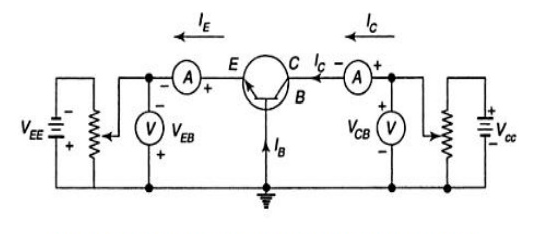
In common base configuration circuit is shown in figure. Here base is grounded and it is used as the common terminal for both input and output.
Characteristics of input:
The characteristic curve that is drawn between the input voltage and the input current while the output voltage remains constant is what it is known as.
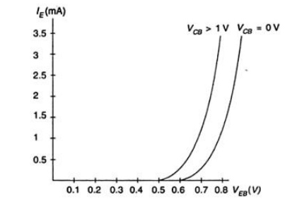
The emitter current IE is increased from zero by increasing VEB in order to determine the input characteristics. This process is repeated for higher fixed values of VCB.
At constant collector base voltage, a curve is drawn between the emitter current and the emitter base voltage. When VCB is zero, EB junctions are forward biased. As a result, it acts like a diode, causing a rapid increase in emitter current.
Output characters
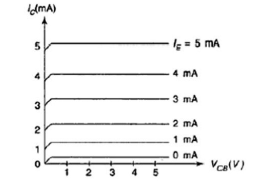
The characteristic curve that is drawn between the input current and the output voltage is referred to as the output characteristics. The collector current Ic is increased from zero by increasing VCB, and the process is repeated for higher fixed values of IE in order to determine output characteristics.
The characteristic reveals that, at a constant value of IE, Ic is independent of VCB and that the curves are parallel to the VCB axis. Since the emitter-base junction is forward biased, the majority of carriers, or electrons, are injected into the base region.
The quasi-neutral width in the base changes when the base-collector voltage changes in a CB configuration. As a result, as the collector-base current rises, the gradient of the minority carrier density in the base shifts, resulting in an increased collector current. The Early effect is the name given to this effect.
2. CE CONFIGURATION
The figure depicts a typical emitter configuration circuit. Here producer is grounded and it is utilized as the normal terminal for both info and result. The grounded emitter configuration is another name for it. The collector is the output terminal, while the base is the input terminal.
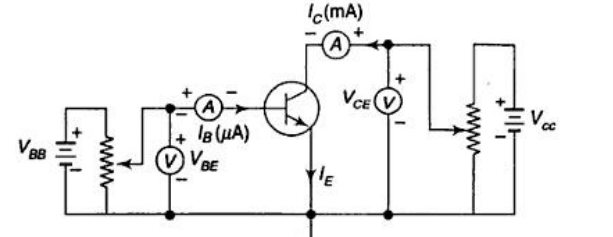
Input Characteristics
It is the characteristic curve that is drawn between input voltages and input current with a constant output voltage.
The collector base voltage VCB is maintained at zero, and the base current IB is increased from zero by increasing VBE. This procedure is repeated for higher fixed values of VCE in order to determine the input characteristics.
Output Characteristics
It is defined as the characteristic curve that is drawn between the input current and the output voltage.
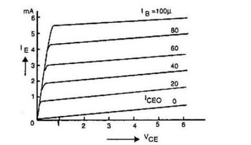
The collector current Ic is increased from zero by increasing VCE in order to determine the characteristics of the output. This process is repeated for higher fixed values of IB.
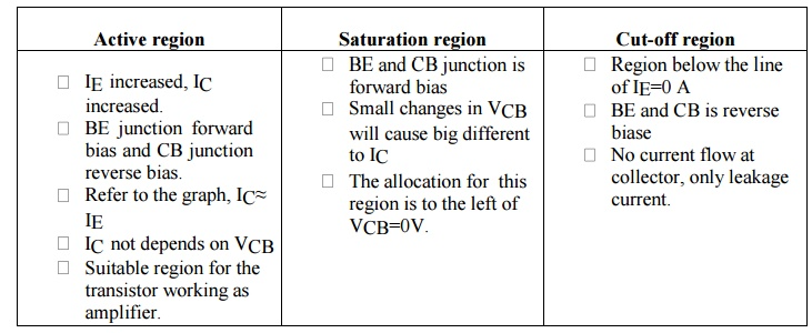
There are three main areas of the output characteristic:
- The biasing arrangements define the active region.
- Saturation region: the region of the characteristics to the left of VCB = 0V; – . Cutoff region: the region where the collector current is 0A.
3. CC CONFIGURATION
The figure depicts a typical collector configuration circuit. The collector in this case is grounded and serves as both the input and output common terminal. The grounded collector configuration is another name for it. Emitter is the output terminal, while base is the input terminal.

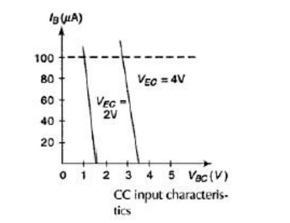
Input Characteristics
The characteristic curve that is drawn between the input voltage and the input current while the output voltage remains constant is what it is known as.
A curve is drawn between base current and base emitter voltage at constant collector base voltage to determine input characteristics. The emitter base voltage VEB is kept constant at zero, and the base current IB is increased from zero by increasing VBC. This process is repeated for higher fixed values of VCE.
Output Characteristics
It is defined as the characteristic curve that is drawn between the input current and the output voltage.
The base current IB is held constant at zero, and the emitter current IE is raised from zero by increasing VEC in order to determine the characteristics of the output. For higher fixed IB values, this is repeated.
The characteristic reveals that the curves are parallel to the axis of VEC and that, for a constant value of IB, IE is independent of VEB.