The MSP430 Development kit is made to help students learn the embedded systems skills they need to succeed. The students will be able to easily utilize all of the microcontroller’s features thanks to the design of the kit. The unit upholds with Code Arranger Studio v4 and later through USB port.
Texas Instrument Microcontroller, MSP430 Improvement pack is proposed to smooth the advancement of creating and troubleshooting of different plans incorporating of speed 16-cycle Microcontrollers. To create a stand-alone, adaptable test platform, it incorporates onboard PS2, UART, ADC, PWM, temperature sensor, relay, buzzer, I2c Seven Segment, I2C Serial EEPROM, temperature sensor LM35, matrix keypad, switch, LED, stepper motor driver, traffic light controller, I2C RTC, LCD, and GLCD display. Client can undoubtedly take part Being developed in this stage, or use it as reference to application Improvement.
Relay
Low-power circuits can use relays to switch a relatively high Current/Voltage ON/OFF. Most of the time, a relay circuit is a smaller switch or device that drives (opens/closes) an electric switch that can handle a lot more current.
Interfacing Relay with MSP430F5529
Fig. 1 demonstrates the microcontroller-relay interface. There are two channels for input. The relay’s triggering coil is connected to each of the inputs. Each of the two output channels corresponds to an input. The relay is activated when the input is energized, and the “+” output is connected to +12 volts. The “+” output is connected to Ground when the relay is turned off. Ground is connected permanently to the “-” output.
Interfacing Relay with MSP430F5529
We presently need to control the transfer activities by utilizing MSP430F5529 Advancement Board. Two Relays are utilized here. There is a coil and a switch in the relay. The switch closes, joining the two contacts together, when the coil is energized. The output of the ULN2803 driver is connected to relay modules on port I/O lines. Connector accommodated outside power supply if necessary.
Module for Relay: Relay module port P1 pins (Realy1 – P3.2) and Relay2-P3.5): raise port pins to high to activate relay.
Pin Assignment with MSP430F5529
Interface Relay with MSP430F5529 MSP430 For the motor/relay section, use jumper JP8 to get power from either an internal (on-board) or external supply.
Circuit Diagram to Interface Relay with MSP430F5529
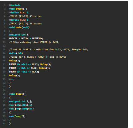
C Program to control Relay in MSP430F5529
Title : Program to control Relay