


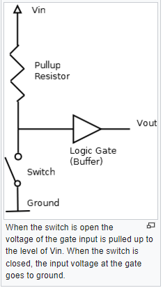
When connecting logic gates to inputs, a pull-up resistor can be used. A resistor, for instance, could pull an input signal, and then a switch or jumper strap could connect that input to ground. This can be utilized for device troubleshooting, option selection, and configuration information.
In electronic rationale circuits, a draw up resistor (PU) or pull-down resistor (PD) is a resistor used to guarantee a known state for a signal.[1] It is commonly utilized in blend with parts, for example, switches and semiconductors, which genuinely interfere with the association of resulting parts to ground or to VCC. When the switch is closed, a direct connection is made to ground or VCC; however, if the switch were to be opened, the remainder of the circuit would remain floating, or its voltage would be uncertain.
A pull-down resistor connected between the circuit and ground ensures a well-defined ground voltage (i.e. logically low) across the remainder of the circuit when the switch is open for a switch that is used to connect a circuit to VCC (for instance, if the switch or button is used to transmit a “high” signal). A pull-up resistor connected between the circuit and VCC ensures a well-defined voltage (i.e. VCC, or logical high) when the switch is open for a circuit-to-ground connection.
Because in the former scenario, the stationary voltage in any loop in which it is involved cannot longer be determined by Kirchhoff’s laws, an open switch is not equivalent to a component with infinite impedance. As a consequence of this, not only are the voltages across those crucial components—like the logic gate in the illustration on the right—undefined, but they are also only present in loops that involve the open switch.
By effectively creating an additional loop over the crucial components, a pull-up resistor ensures that the voltage is well-defined even when the switch is open.
A resistor with the right amount of resistance must be used so that a pull-up resistor can only be used for this one purpose and not interfere with the circuit in any other way. This assumes that the critical components have an impedance that is either infinite or sufficiently high, as is the case with logic gates made of FETs, for instance. The circuit appears to be a wire connected to VCC when the switch is open, and the voltage across a pull-up resistor with sufficient impedance virtually disappears. In contrast, the pull-up resistor must have a sufficiently high impedance relative to the closed switch for it to not affect the connection to ground when the switch is closed. The pull-up resistor’s impedance can be determined by combining these two conditions, but typically only a lower bound is established by assuming that the critical components do indeed have infinite impedance. A resistor with a low resistance in relation to the circuit in which it is located is frequently referred to as a “strong” pull-up or pull-down. The circuit will draw more current when it is open, but it will pull the output high or low very quickly, just like the voltage changes in an RC circuit. A “weak” pull-up or pull-down resistor is one with a low resistance. When the circuit is open, it will draw less current but pull the output high or low more slowly. Keep in mind that this current, which is essentially energy wasted, only flows when the switch is closed, and technically only for a short time after it is opened, until the circuit’s charge has been released to ground.
Applications
When connecting logic gates to inputs, a pull-up resistor can be used. A resistor, for instance, could pull an input signal, and then a switch or jumper strap could connect that input to ground. This can be utilized for device troubleshooting, option selection, and configuration information.
At logic outputs where the logic device cannot supply current, such as open-collector TTL logic devices, pull-up resistors can be used. Such results are utilized for driving outside gadgets, for a wired-OR capability in combinational rationale, or for a straightforward approach to driving a rationale transport with different gadgets associated with it.
Pull-up resistors can be discrete components that are integrated into the same circuit board as logic components. As a result of their internal, programmable pull-up resistors for logic inputs, many embedded control microcontrollers do not require many external components.
The slower speed of a pull-up resistor when compared to an active current source and the additional power that is consumed when current is drawn through the resistor are two of the draw-up resistor’s drawbacks. Pull-up resistors can introduce power supply transients into logic inputs for some logic families, necessitating the use of a separate filtered power source for the pull-ups.
Because the inputs are voltage-controlled, pull-down resistors can be used safely with CMOS logic gates. TTL rationale inputs that are left un-associated intrinsically float high, and require a much further esteemed pull-down resistor to compel the info low. In most cases, a pull-up resistor of no more than 50 kohms is sufficient to operate a standard TTL input at logic “1” with a source current of 40 A. whereas the TTL input at logic “0” is anticipated to sink 1.6 mA at a voltage below 0.8 V, necessitating a pull-down resistor of less than 500 ohms[2]. Lowering the voltage on unused TTL inputs draws more current. In TTL circuits, pull-up resistors are therefore preferred.
In bipolar rationale families working at 5 VDC, a run of the mill pull-up resistor worth will be 1000-5000 Ω, in light of the prerequisite to give the expected rationale level current over the full working scope of temperature and supply voltage. Because the required leakage current at a logic input is small, much higher values of resistor, ranging from several thousand to a million ohms, can be used for CMOS and MOS logic.