


1. What is a Logic Gate?
Rationale doors are little computerized electronic gadgets that carry out a Boolean role with two sources of info and give a result. Binary data make up the data. Logical 0 is false or low, while logical 1 is true or high. The logical operation and the output vary depending on the logical gate. A truth table that lists all possible input and output combinations is followed by each logic gate.
What is a Logic Gate? Every logic gate works in a way that is easy to understand and resembles the addition and multiplication operations that we are already familiar with from regular math. Similar to a light switch, a logic gate turns on when the output is one and off when the production is zero. Logic gates take on the form of a variety of electronic devices and are utilized alongside diodes, transistors, and relays. Small-scale logic gates were utilized in the production of some of the most widely used families of transistors, such as the TTL 7400 series from Texas Instruments and the CMOS 4000 series.
2. Logic Gate Types and Truth Tables
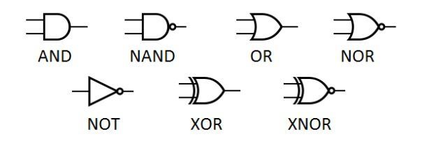
The logic gates’ underlying symbol representation was shown in a table format for your convenience. An article provides an overview of symbols for logic gates.
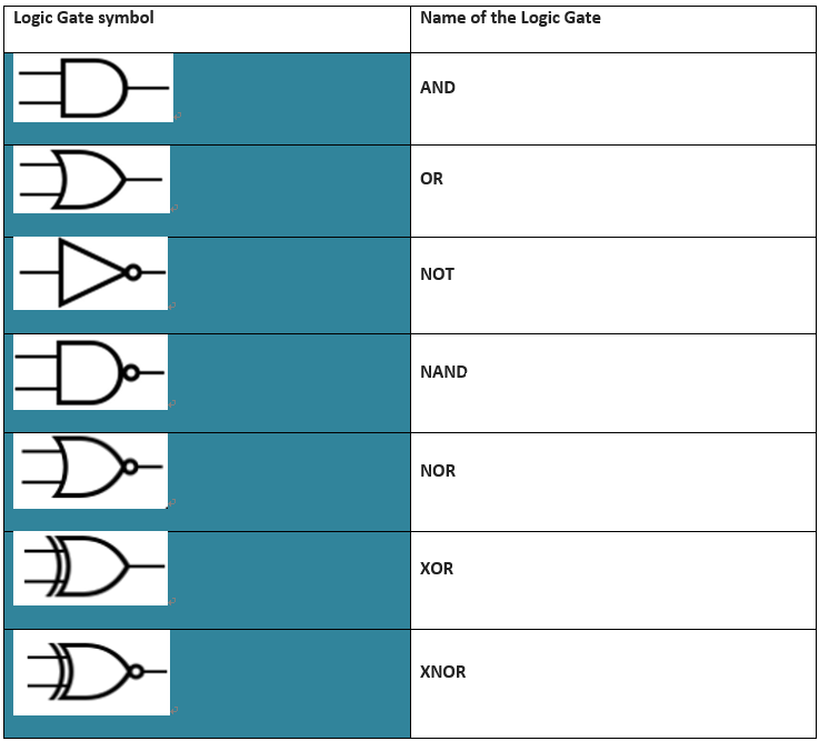
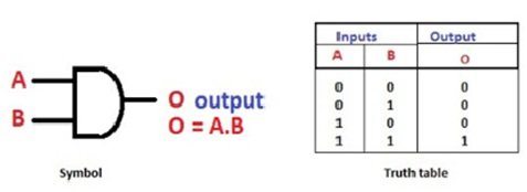
AND Gate
Because you can derive some of the upcoming logic gates like NAND from it, the AND gate can be included in the primary logic gate category. It performs the Dot (.) or multiplication operation based on logical inputs As can be seen, O is kept as the output while A and B are the two inputs that are fed to the terminals. The truth table of an AND gate shows that the output is high only when both inputs are high; otherwise, the output is low.
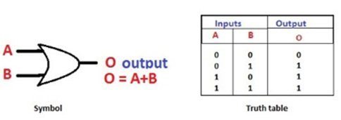
OR Gate
Or on the other hand door is a fundamental entryway dissimilar to AND as XOR and XNOR can be acknowledged from it. With the inputs, the OR gate performs a straightforward addition or “+” operation. When both inputs are 0, the output is low, or 0; otherwise, it is high, or logical 1, in all other cases.
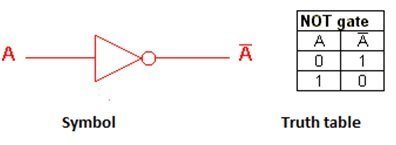
NOT Gate
Or on the other hand door is a fundamental entryway dissimilar to AND as XOR and XNOR can be acknowledged from it. With the inputs, the OR gate performs a straightforward addition or “+” operation. When both inputs are 0, the output is low, or 0; otherwise, it is high, or logical 1, in all other cases.
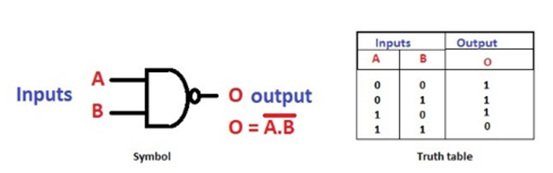
NAND Gate
What’s more, entryway followed by a NOT door is the real idea driving the NAND rationale door, one among the all inclusive doors. The output at the other terminal is the resultant when the AND gate’s output is inverted. To learn more about the NAND operation, refer to the truth table below.
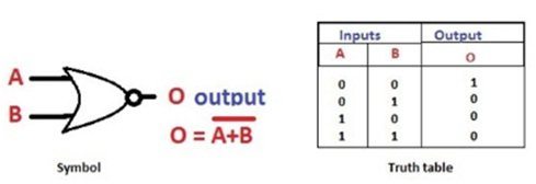
NOR Gate
A universal logic gate, NOR is the combination or inversion of the logical OR gate. The output is high or true when the inputs are low or false.
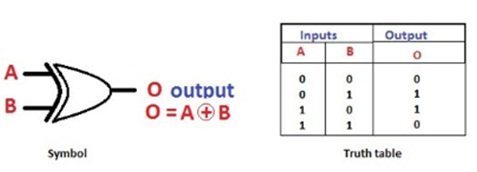
XOR Gate
Exclusive NOR gate is another name for the XOR gate. The truth table of XOR can be observed to show that the result is high or true if any input is high
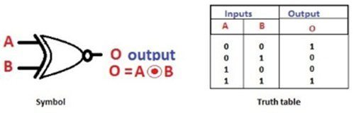
XNOR Gate
XNOR or Exclusive NOR gate’s basis its operation on the NOR gate. When there is an inversion on the NOR gate, you get the XNOR gate. The output is just opposite to that of the XOR gate. If anyone of the input is high, excluding the condition of both, the output is low
Logic Gate Analysis’s Benefits
Logic gates are found in the majority of the electronic circuits or devices we use every day.
Logic gates are used in every modern digital device, including laptops, computers, tablets, and mobile phones. Take, for instance, the memory in a computer.
Because logic gates can store data, they are combined to form a “Latch” circuit. When driven by clock signals, these circuits become “Flip-flops.”
They are responsible for the speed and complexity and are referred to as sequential logic or combinational logic.
Tri-state logic gate, a more advanced variant that supports plug-ins as well as multiple operations, can be found in the CPU and buses.
CMOS, in which logic gates serve as the fundamental building blocks, is the emerging microchip development technology at the moment.
There are more than 100 million gates in the technical microprocessors that are used in logical circuits.
Use Cases for Logic Gates
Electronic Equipment: It should be noted that digital circuits and logic gates are found in every electronic device we use today. A logic gate circuit is still the most important component of any digital circuit, even though it carries out fundamental logical operations. Logic gates are responsible for making decisions based on digital input. After that, it provides one of two outputs—true or false—to simplify the input. A logic gate works like a light switch, to put it simply.
Industrial Facilities: In industrial facilities, logic gates are frequently utilized as safety parameters. Any system action is detected by an OR gate. It informs us of any unforeseen occurrences. This way, logic gates show when the safe value for any parameter is breached or exceeded. It provides the result; It suggests that some preventative measures should begin to bear fruit. A straightforward illustration is when logic gates signal a rise in temperature in a plant to take action.
Measurement of Frequency: A logic gate can also be used to measure a wave’s or pulse’s frequency. One of the rationale doors, the AND entryway, is additionally usually known as the empower entryway. It means that it stops all other waves and lets only waves with a certain frequency pass through. Because it reverses the input and returns it as the output, the NOT gate is also frequently utilized as an inventor.
Logic Gates’ Limitations
Despite their widespread use, logic gates have some drawbacks:
Realization of logic gates is not possible for designs of more complex systems or circuits because it may be difficult to correctly position and connect them.
Implementations of logic gates use more energy than is necessary for most circuits.
Battery power systems or portable power sources are required for logic circuits.
The Logic Gates Story
First and foremost, Gottfried Leibniz improved the binary system concept. In 1705, he also suggested that the binary number system could be used to combine logical and arithmetic principles. George Boole came up with the idea of Boolean algebra in later 1854, which uses a consistent method of comparing numbers to make decisions. His work was then published in the book “An Investigation of the Laws of Thought on Which the Mathematical Theories of Logic and Probabilities Are Based.” He wanted to demonstrate how human reasoning can be represented in mathematical form.
Charles Peirce later introduced the idea of logical operation in the electrical switching circuit in 1886. Fleming valves were used as logic gates, and vacuum tubes took the place of relays in 1907. For developing the first modern electronic AND gate in 1924, Walther Bothe won the Nobel Prize in Physics in 1954. Claude Shannon then refered to the idea of Boolean variable based math in 1937 for the plan of exchanging circuits. Still, molecular logic gate development relies heavily on research and analysis.
Logic Gate Illustrations
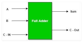
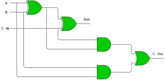
One excellent illustration of this is the full adder. Sum and Carry are two of the two outputs of a full adder’s three inputs. It performs the addition operation on the given data, making it popular for use in calculations. When compared to the switching time of analog circuits, this process takes place in seconds. Other adder applications utilized in digital channels include carry-look-ahead, BCD, and half adders.
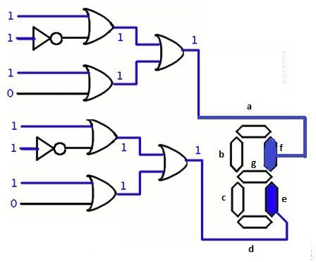
Calculator Display of Segments
Trust you have utilized adding machines and our next model portrays the mixes of rationale doors. Even though we provide numbers as our input, this is what happens inside the device. The display’s segments a, b, c, d, e, f, and g are all connected to a set of logical gate connections. When you press 1 on the interface, for instance, the process described below occurs, and the segments f and e are highlighted or glow on the display.
How to Use EdrawMax to Create a Logic Gats
You should know exactly what the circuit needs before starting the design process, and you should plan where to put them to avoid misunderstandings. You can also request design post, which will make your process much simpler in a matter of minutes.
Step 1: Sign in to EdrawMax Online or download the software to your device and launch it.
Step 2: Open the software by selecting the “Libraries” option from the toolbar after completion.
Step 3: You will see options like “Analog and digital logic” and “Integrated circuit components” when you select “Circuits and logic diagram.”
Step 4: From the library, select the “Analog and digital logic” option and begin designing your analog circuit with the logic gate functions on the left.
Step 5: You can set up a gate by clicking the configuration button after inserting it. The gate type, input, and output can all be changed.
FAQ: Logic Gate
How is a logic gate operated?
The movement of electric current is the function of a logic gate. You must input it, and if the transfer is on, the current can pass through it. The conditions for the current flow that you are using as a switch are typically described by the logic gate. Binary operations like addition, multiplication, and division are possible with logic gates.
Which of the seven Logic Gates is it?
The seven fundamental gates of logic are AND, OR, NOT, NAND, NOR, XNOR, and XOR. Different binary operations are carried out by each of these gates. Take the AND gate for instance. When all of the inputs are true, it returns true as the output; The OR gate, on the other hand, returns true if either of the inputs is true.
How do I switch from Logic to NAND gates?
Any logic gate can be changed with the NAND gate. NAND gate will act as NOT gate if you give it the same input. An AND gate is formed when a NAND gate has two inputs and the output is used as an input to another NAND gate. You will get the same output as an OR gate if you give one input to one NAND gate and another input to another NAND gate and then use both of their outputs as input for a new NAND gate.
Related Posts
What is UML: Everything You Need to Know About The Project Calendar Everything You Need to Know About The Network Diagram Work Breakdown Structure (WBS) for Dummies What Is A Gantt Chart Free Online UML Diagram