


A full wave rectifier is an electronic circuit that converts an alternating current (AC) signal into a direct current (DC) signal by allowing both the positive and negative portions of the AC signal to be used to create a DC signal. There are two types of full wave rectifiers: center-tapped and bridge. They are commonly used in power supplies for electronic devices and other applications where a DC signal is needed from an AC input.
What is the basic types of full wave rectifiers?
The full wave rectifier is further classified into two types: center tapped full wave rectifier and full wave bridge rectifier.
What are the two types of full wave rectifier?
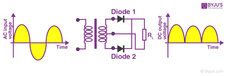
The full-wave rectifier converts AC voltage into DC voltage. It converts positive and negative cycles of AC voltage into DC voltage. The center-tapped rectifier and bridge rectifier are two types of full-wave rectifiers.
What is half and full-wave rectifier?
The half-wave rectifier is a rectifier which is used for converting the one-half cycle of AC input to DC output. A full-wave rectifier is a rectifier which is used for converting both the half cycles of AC input into DC output.
How many diodes are in a full wave rectifier?
For example, for a three-phase AC input, a half-wave rectifier consists of three diodes, but a full-wave bridge rectifier consists of six diodes.
Types of Full Wave Rectifiers
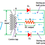
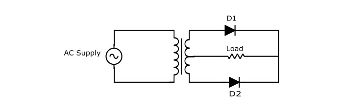
Full Wave Bridge Rectifier Centre Tap Full Wave Rectifier The circuit of a center tap full wave rectifier is made up of the following main components: two diodes; a centre-tapped transformer; a load resistance.
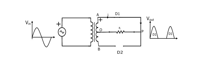
Positive Half Cycle of the Center-Tap FWR Circuit During the positive half cycle of the input AC voltage, the secondary winding’s end A becomes positive and the end B becomes negative. As a result, diode D1 is biased forward, making it a closed switch, and diode D2 is biased backward, making it an open switch. As a result, current travels from P to O through the load (RL).
Negative Half Cycle During the input AC supply’s negative half cycle, the secondary winding’s end B becomes positive and the end A becomes negative. This makes the diode D2 forward one-sided (behaves like shut switch) and the diode D1 invert one-sided (goes about as open switch). As a result, the lower half of the secondary winding, load RL, and diode D2 will carry the current from
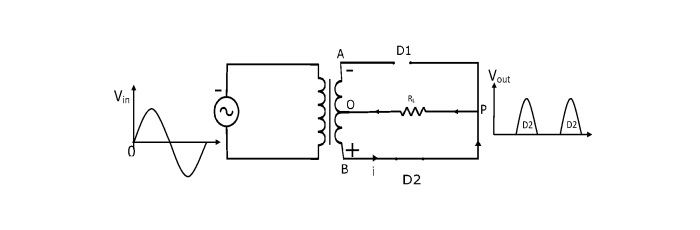
Note that the ongoing through the heap is in similar heading for both half patterns of information AC supply. This results in DC output across the load.
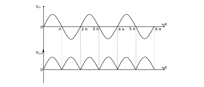
The output frequency of the center tap FWR is twice that of the input frequency. Because the supply at the input is a sine wave that repeats every 2 radians, Pulsating DC is the output of FWR, and it repeats the same pattern twice every 2 radians as the input AC.
fout=2fin The diodes must have a peak inverse voltage, which is one of the drawbacks of the center-tap FWR.
On the secondary winding, it is difficult to locate the center tap.
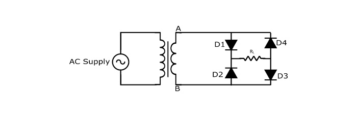
The use of a full wave bridge rectifier eliminates the requirement for a center tapped transformer. It is a bridge made up of four diodes connected together.
The following are the primary components of the full wave bridge rectifier’s circuit: four diodes; a step down transformer; load resistance
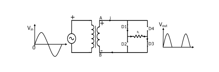
The Center-Tap FWR Circuit’s Operation
Positive Half Cycle During the input AC voltage’s positive half cycle, the secondary winding’s end A becomes positive and the end B becomes negative. As a result, diode D1 is biased forward, making it a closed switch, and diode D2 is biased backward, making it an open switch. As a result, current travels from P to O through the load (RL).
Negative Half Cycle During the negative half cycle, the secondary winding’s end A changes into a negative value and the end B becomes a positive value. As a result, diodes D1 and D3 are biased in the opposite direction—much like an open switch—while diodes D2 and D4 are biased in the opposite direction. Through diode D2, load RL, and diode D4, current flows from B to A.
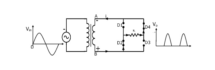
For both input AC supply cycles, therefore, the current flows in the same direction through load RL. As a result, DC output is produced throughout the load.
Advantages of Bridge FWR: For the same secondary voltage, its output is twice as big as that of a center tap full wave rectifier.
Center-tapped transformers are unnecessary.
The PIV of a full wave bridge rectifier is half that of a Centre-Tap FWR for the same DC output.
The drawbacks of the Bridge FWR are that it needs four diodes.
The two diodes that conduct are in series with each half cycle of the AC input, resulting in a voltage drop in the diodes’ internal resistance.
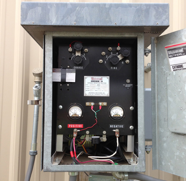
What are the components of a rectifier?
There are three major components in a rectifier: transformer, stack, and cabinet. The purpose of the transformer is to safely separate the incoming AC voltage (primary side) from the secondary side, which is adjusted to control the output voltage of the rectifier.
What is the main application of full wave rectifiers?
Full-wave rectifiers are used for the conversion of AC voltage to DC voltage whic hrequires multiple diodes to construct. The process of converting an AC signal to a DC signal is known as full wave rectification. Electrical circuits called rectifiers convert alternating current (AC) to direct current (DC).
What is the function of full wave rectifier in Electric Vehicles?
In electric vehicles, a full wave rectifier is used to convert the alternating current (AC) power from the charging station or power source into direct current (DC) power that can be used to charge the vehicle’s battery pack. The full wave rectifier ensures that the DC voltage delivered to the battery pack is smooth and consistent, which helps to maximize the charging efficiency and prolong the battery life.
The full wave rectifier is a key component of the charging system in electric vehicles and is responsible for converting the AC power from the grid or charging station into a suitable DC voltage for charging the battery. It also helps to regulate the charging current and prevent damage to the battery from overcharging or fluctuations in the charging voltage.
Overall, the function of a full wave rectifier in electric vehicles is to convert the AC power input into a smooth and consistent DC voltage that is suitable for charging and maintaining the battery pack, which is critical for the reliable and efficient operation of the vehicle.
Advantages of Full Wave Rectifier:
The advantages of a full wave rectifier include:
- Higher efficiency: Full wave rectifiers are more efficient than half wave rectifiers as they utilize both halves of the AC input signal.
- Smoother DC output: Full wave rectifiers produce a smoother DC output compared to half wave rectifiers, which can result in less ripple voltage.
- Increased frequency: Full wave rectifiers can double the frequency of the input signal, which can be beneficial in certain applications.
- Less interference: Full wave rectifiers generate less electromagnetic interference (EMI) than half wave rectifiers because they utilize both halves of the input signal, resulting in a more consistent output.
- More suitable for high power applications: Full wave rectifiers are better suited for high power applications as they can handle higher currents and voltages.
Overall, full wave rectifiers are a more efficient and reliable method for converting AC to DC power than half wave rectifiers.