


A straightforward circuit known as a voltage divider reduces a large voltage to a smaller one. We can produce an output voltage that is only a small fraction of the input voltage with just two series resistors and an input voltage. One of the most fundamental electronic circuits is the voltage divider. Learning about voltage dividers would be like learning how to spell cat if learning Ohm’s law was like learning the ABCs.
These are examples of potentiometers, which are variable resistors that can be used to make a voltage divider that can be adjusted. We will soon learn more about these.
Using voltage dividers, you can get different voltage levels from the same supply voltage. This common supply can be a single positive or negative supply, such as +5V, +12V, -5V, or -12V, and so on. in relation to a common point or ground, typically 0 V, or in relation to a dual supply, such as 5 V or 12 V, etc.
Because the voltage unit, the “Volt,” represents the amount of potential difference between two points, voltage dividers are also referred to as potential dividers. A straightforward passive circuit known as a voltage or potential divider makes use of the effect of voltage drops across components that are connected in series.
The most fundamental type of voltage divider is the potentiometer, which is a variable resistor with a sliding contact. We can apply voltage to its terminals and generate an output voltage proportional to the mechanical position of its sliding contact. As two-terminal components that can be connected in series, however, resistors, capacitors, and inductors can also be used to create voltage dividers on their own.
Resistive Voltage Dividers
The circuit here is made up of two resistors connected in series: R1, and R2. Since the two resistors are connected in series, the circuit’s resistive elements must all carry the same value of electric current because there is nowhere else for it. As a result, an I*R voltage drop is displayed for each resistive element.
We can use Kirchhoff’s Voltage Law (KVL) and Ohm’s Law to determine the voltage dropped across each resistor in terms of the common current I flowing through them with a supply or source voltage VS applied across this series combination. So tackling for the current (I) moving through the series network gives us:
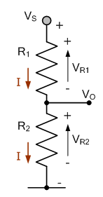

In accordance with Ohm’s Law, the current flowing through the series network is simply I = V/R. In the above series circuit, the voltage dropped across resistor R2 can be calculated as follows because the current flows through both resistors (IR1 = IR2):
Across the supply voltage, each resistance produces an IR voltage drop proportional to its resistive value. We can see that the largest resistor results in the greatest IR voltage drop by applying the voltage divider ratio rule. As a result, R1 = 4V and R2 = 8V. Applying Kirchhoff’s Voltage Law reveals that the sum of the voltage drops around the resistive circuit is exactly equal to the supply voltage, as 4V + 8V = 12V. Note that the voltage dropped across each resistor would be exactly half the supply voltage for two resistances connected in series because the voltage divider ratio would be 50%.
A voltage divider network can also be used to generate a variable voltage output. The voltage dropped across resistor R2 can be controlled by adjusting the position of the potentiometer’s wiper and the ratio of the two resistive values by substituting a variable resistor (potentiometer) for resistor R2. This allows us to control VOUT in a manner that is dependent on the position of the potentiometer’s wiper. Variable voltage division devices include potentiometers, trimmers, rheostats, and variacs.
By substituting a sensor like a light dependent resistor, or LDR, for the fixed resistor R2, we could also take this concept of variable voltage division one step further. As a result, the output voltage VOUT changes in proportion to the sensor’s resistive value as light levels change. Other examples of resistive sensors include thermometers and strain gauges.
Mathematically, there must be a connection between the two voltage division expressions above because they both refer to the same common current. Therefore, the voltage dropped across any given resistor in a series network of any number of individual resistors is expressed as:
Voltage Dividers Equation
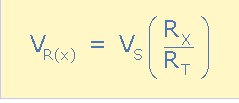
Where: The voltage drop across the resistor is VR(x), the resistor’s value is RX, and the series network’s total resistance is RT. Due to the proportional relationship between each resistance, R, and its corresponding voltage drop, V, this voltage divider equation can be applied to any number of series resistances connected together. However, keep in mind that this equation only applies to an unloaded voltage divider network without any additional connected resistive loads or parallel branch currents.
Voltage Dividers Example No2
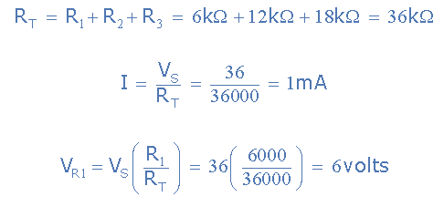
Over a 36-volt supply, three resistive elements of 6k, 12k, and 18k are connected in series. Determine the voltage drops across each resistor, the value of the circuit’s current, and the total resistance.
Data provided: R1 is 6k, R2 is 12k, and R3 is 18k, with VS being 36 volts.
Voltage Dividers Circuit
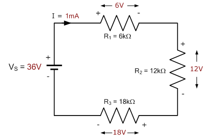
According to Kirchhoff’s Voltage Law (KVL), the voltage drops across all three resistors ought to add up to the supply voltage. The sum of the voltage drops is therefore: VT is correct because it is the same as the supply voltage, VS, which is 36.0 V. Recall that the greatest voltage drop is caused by the largest resistor.
A Divider Network’s Voltage Tapping Points Consider a long series of resistors connected to a voltage source, VS. These points are called voltage taps in a voltage divider network. A, B, C, D, and E are the various voltage tapping points along the series network. The total series resistance, or RT value of 15k, can be calculated by adding the individual series resistance values together. This resistive value will restrict the flow of current produced by the supply voltage, VS, through the circuit.
Using the aforementioned equations, the individual voltage drops across the resistors are calculated as follows: VR1 = VAB, VR2 = VBC, VR3 = VCD, and VR4 = VDE.
With respect to the ground, the voltage levels at each tapping point are measured. As a result, VDE will be the voltage level at point D, and VCD + VDE will be the voltage level at point C. To put it another way, the voltage at point C is equal to the sum of the voltage drops at R3 and R4.
As a result, we can hopefully see that we can generate a series of voltage drops with a proportional voltage value obtained from a single supply voltage by selecting a suitable set of resistive values. Because the voltage supply’s negative terminal, VS, is grounded, each output voltage point in this example will have a positive value.