


The increasing demand for electric vehicles (EVs) is seeing manufacturers developing and releasing more affordable models. The most important factor when designing EV batteries or battery management systems (BMSs) is safety. Safety is collectively pursued in industry via stringent regulation and certification and ensured through testing.
In this article, we’ll take a high-level view of which factors battery standard tests cover for electric vehicle battery systems.

EV batteries require thorough testing to ensure they’re safe enough for commercial use. Image used courtesy of UL (Underwriter Laboratories).
Why EV Battery Testing Matters
Since cars consume large amounts of power only battery technologies with high power densities are desirable and because cars need to be used on a daily basis the battery must be rechargeable. However, their greater energy storage capability (resulting from the use of reactive metals), means that they can be more destructive should they fail.
During failure, a lithium-based battery can release large quantities of hydrogen gas and the intense heat caused by an internal short-circuit will ignite the hydrogen effectively creating a flamethrower. Since cars are at risk of damage from collisions, it is essential that batteries contain multiple safety mechanisms to ensure that under no circumstance can the battery ignite.

“Safety strategies” for each EV system level, as laid out by a GM presentation for the United Nations Economic Commission for Europe in 2013
EV Testing Parameters
Like with any engineering project the first step is to always understand the environment that your product is expected to survive in.
The automotive industry is far from forgiving so what factors would need to be considered with regards to batteries?
- MechanicalMechanical stress and effects are very profound in the automotive industry due to the constant motion of wheels, and uneven surfaces that the vehicle may be in contact with. Therefore, a battery system must be able to handle these vigorous vibrations for long periods of time. Vehicle collisions are also a real threat and any battery system that experiences such an event must be able to either survive or break graciously. It is essential that any impact or stress applied to the battery system does not cause a fire or leak explosive gasses.
- TemperatureWhile electric vehicles do not have engines, the large currents drawn from the batteries will lead to temperature increases. These batteries, however, may also be expected to survive very low temperatures depending on where the vehicle is used. But temperature swings can happen daily too with cold nights and hot days which could see frequent thermal stresses that will need to be considered. If the vehicle is left in the sun and not in use then designers may need to consider if automated cooling systems are required which are never disengaged.
- ElectricalUnder normal conditions, designers will be able to determine the current draw from the batteries to the motors and thus make determinations on cable size and fuse settings. However, many other electrical factors need to be considered that may have serious impact on the battery. For one, the rate of change of voltage on the batteries during charging and discharging can cause overheating. Another factor to consider would be voltage spikes from the mains supply during grid faults which can cause serious damage to the battery system.
Types of Testing for Compliance
There are many standards in place for electric vehicles that are dictated by regulatory bodies. The ISO has over 40 standards published which cover safety from the level of individual components all the way up to V2X protocols. UL (Underwriter Laboratories) is another regulatory body that puts forth codified rules for battery testing, including UL 2580, which is concerned with electric vehicle battery safety and lays out requirements of how those batteries must be able to tolerate a wide spectrum of abuse.
While there are many standards and regulators, the tests designed for battery safety are all focused on ensuring that EV batteries can withstand various environments and conditions that could cause safety issues.
These conditions include:
- Standard thermal tests – Storage at various temperatures, etc.
- Thermal abuse – Withstand sudden high temperatures, etc.
- Loss of thermal cooling – Withstand lack of cooling
- Mechanical vibration – Withstand vehicle vibrations
- Mechanical shock – Withstand sudden shocks
- Mechanical impact and crush – Measure how the battery will cope with being crushed in a collision
- Mechanical penetration – Withstand being penetrated (i.e., short cells)
- Electrical short circuit – Handle being shorted
- Electrical overcharge – Overcharging does not cause damage to the battery or lead to a fault
- Electrical force discharge – Determine if rapid discharge causes damage via gas build-up etc.
- EMC susceptibility – Withstand sources of EM interference
- High voltage protection – Protection from sudden high voltages
- Electrical shutdown integrity – Ensure that shutdown separators function correctly
- Electrical imbalance charging – Ensure that the battery is safe during imbalanced charging
- Environmental – Survive altitude, moisture, humidity, and fire
- Water immersion – Ensure that the battery remains safe during water immersion
Conclusion
Standards are put in place to ensure that not only do designs use common compatible hardware and software solutions but to ensure that they meet a minimum level of safety. Electric battery systems are arguably more prone to fault and damage when compared to their engine/fuel counterparts as they are very sensitive to shock, vibration, temperature swings, and penetration. Therefore, it is essential that strict standards are followed when you incorporate electric battery systems to ensure that they remain safe in even the most hostile scenarios.
ALL ABOUT BMS (Battery Management System)
Nowadays, Li-ion batteries reign supreme, with energy densities up to 265 Wh/kg. They do, however, have a reputation of occasionally bursting and burning all that energy should they experience excessive stress. This is why they often require battery management systems (BMSs) to keep them under control.
In this article, we’ll discuss the basics of the BMS concept and go over a few foundational parts that make up the typical BMS.
Basic BMS Configurations
In Figure 1, we see the basic blocks of how a BMS can look while serving the function of preventing major battery malfunctions.
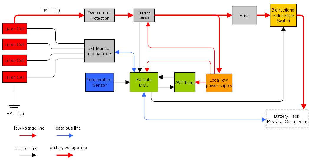
Figure 1. A typical BMS block diagram
This example BMS can handle four Li-ion cells in series. A cell monitor reads all the cell voltages and evens out the voltage among them: this function is called balancing (more on that later). This is controlled by an MCU that handles telemetry data, as well as switch manipulation and balancing strategy.
In practice, the market offers different solutions for simpler designs, including for single cells with no balancing or MCUs, as shown in Figure 2.
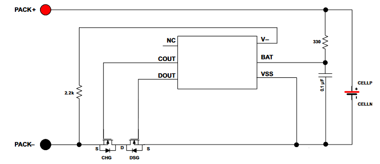
Figure 2. A simple battery manager. Image used courtesy of Texas Instruments
The downside of these simpler systems is that a designer is bound to what the given part offers (e.g., a high or low side switch) without customization.
When using more cells, a balancing system is needed. Simple schemes that still function without an MCU exists, as shown in Figure 3.
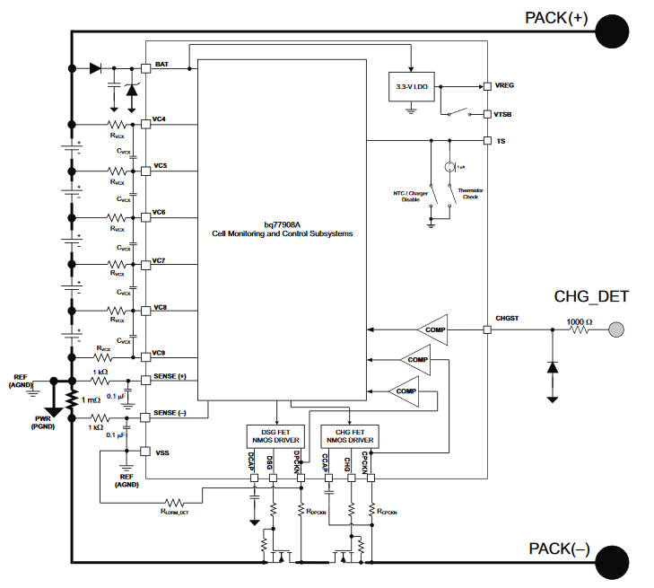
Figure 3. An MCU-independent cell balancer. Image used courtesy of Texas Instruments
When using bigger battery packs or anything which requires cells in series or a fuel gauge calculation, an MCU is needed. The most integrated (and therefore low cost) solution is the one in Figure 4.
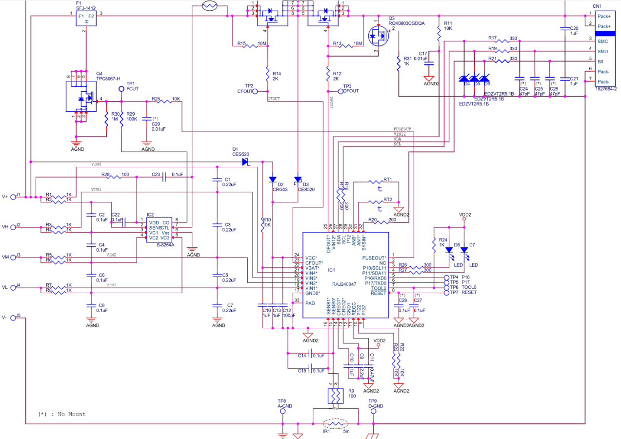
Figure 4. A commercial BMS. Image used courtesy of Renesas
This is a BMS that uses an MCU with proprietary firmware running all of the associated battery-related functions.
The Building Blocks: Battery Management System Components
Look back at Figure 1 to get an overview of the fundamental parts crucial to a BMS. Now, let’s go through the main parts of Figure 4 in a bit more detail to understand the various elements involved in a BMS block diagram.
Fuse
When a violent short circuit occurs, the battery cells need to be protected fast. In Figure 5, you can see what’s known as a self control protector (SCP) fuse, which is mean to be blown by the overvoltage control IC in case of overvoltages, driving pin 2 to ground.
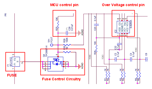
Figure 5. SCP fuse and control of a commercial BMS
The MCU can communicate the blown fuse’s condition, which is why the MCU power supply has to be before the fuse.
Current Sensing/Coulomb Counting
Here is implemented a low side current measurement, allowing direct connection to the MCU.
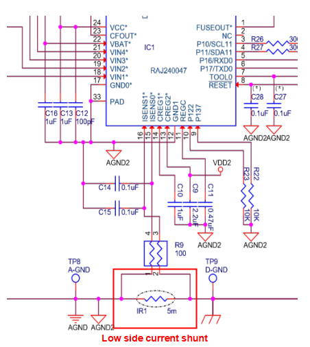
Figure 6. Typical low current sense of a commercial BMS
Keeping a time reference and integrating the current over time, we obtain the total energy entered or exited the battery, implementing a Coulomb counter. In other words, we can estimate the state of charge (SOC, not to be confused with a system-on-chip) by using the following formula:

where
- SOC(t0)SOC(t0) is the initial SOC (in Ah)
- CratedCrated is the rated capacity (in Ah)
- IbIb is the battery current
- IlossIloss takes into account the cell reaction losses
- τ is the averaging period of the electric current samples
Thermistors
Temperature sensors, usually thermistors, are used both for temperature monitor and for safety intervention.
In Figure 7, you can see a thermistor that controls an input of the overvoltage control IC. This artificially blows the SCP (the fuse shown in Figure 5) without MCU intervention.
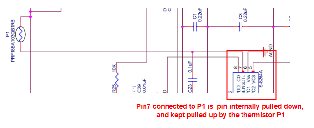
Figure 7. A thermistor can control the SCP, in case of severe thermal problems
Figure 8 shows two additional thermistors for telemetry.
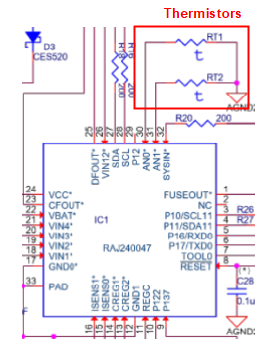
Figure 8. Thermistors used by the firmware
Main Switch
To act as switches, MOSFETs need their drain-source voltage to be Vds≤Vgs−VthVds≤Vgs−Vth. The electric current in the linear region is Id=k⋅(Vgs−Vth)⋅VdsId=k⋅(Vgs−Vth)⋅Vds, making the resistance of the switch RMOS=1/[k⋅(Vgs−Vth)]RMOS=1/[k⋅(Vgs−Vth)].
It’s important to drive the VgsVgs accordingly to ensure low resistance and hence low losses.
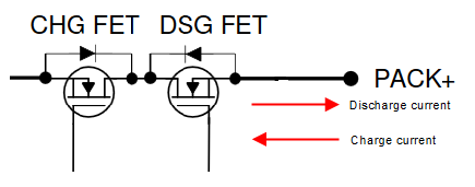
Figure 9. Battery pack main switch (NMOS, high-side)
NMOS types are used also on high side switches through a charge pump, since normally they have lower RMOSRMOS.
Balancer
Battery cells have given tolerances in their capacity and impedance. So, over cycles, a charge difference can accumulate among cells in series.
If a weaker set of cells has less capacity, it will charge faster compared to others in series. The BMS has to therefore stop other cells from charging, or else the weaker cells will get overcharged, as seen in Figure 10.
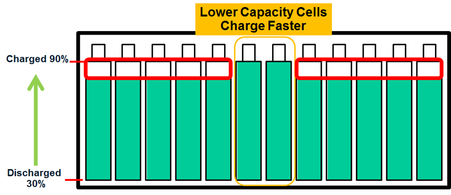
Figure 10. Lower capacity cells impeding pack full charging. Image used courtesy of Analog Devices
Conversely, a cell can get discharged faster, risking that cells going under its minimum voltage. In this instance, a BMS without a balancer has to stop the power delivery earlier, as seen in Figure 11.
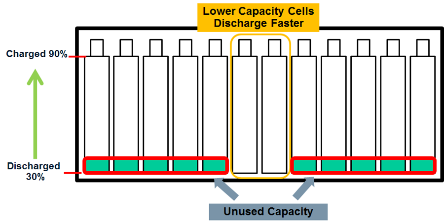
Figure 11. Lower capacity cells impeding usage of full pack energy. Image used courtesy of Analog Devices
A circuit like the one in Figure 12 will discharge the cell with higher SOC (state of charge) as shown in Figure 10 at the level of the other cells in series. This is accomplished by using a passive method of balancing called charge shunting.
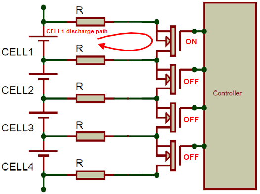
Figure 12. Example of passive balancing strategy
Because current flows through the transistor in the ON state and dissipates through R, and because the voltage reference is CELL1 (a negative pole), only such a cell will discharge its energy excess.
This article has aimed to introduce the basic concept of a battery management system and introduce the basic components used in their design. Hopefully, you now have a better understanding of what a battery management system is meant to accomplish and how it can be used in a power design.
Learn More.