


Despite being one of the oldest types of electric motors, DC motors are still used in modern industry. How have they held up over the years, particularly when compared to all of the amazing new machines of the 21st century?
There are numerous possible responses to this question, but DC motors’ excellent controllability is a major reason why they have endured. By simply reversing its leads or changing the input voltage, this straightforward machine converts DC current into mechanical rotation. Many DC motor controllers have been made because DC motors are so beautiful. These controllers are usually easy to make and perform well for the money. In this article, we’ll look at some common DC motor controllers, how they function, and the most common uses for these systems.
What are DC motor controllers?
A DC motor controller is any device that can change a DC-powered motor’s position, speed, or torque. Even though their mechanisms for doing so differ, controllers for universal motors, brushed DC motors, and brushless DC motors all permit operators to set the desired motor behavior.
Our articles on shunt DC engines, series wound DC engines, and brushless DC engines give nitty gritty clarifications on how DC machines capability. To momentarily sum up, the speed/force bend of DC engines are conversely straight, meaning their force relatively diminishes as the engine RPMs increment. Because decreasing the speed will result in an increase in torque, this makes controlling the vehicle simple. Additionally, in contrast to some AC motors, DC motors can be reversed by simply switching their leads so that the DC current flows in the opposite direction. This article will look at the most common ways that DC motor controllers make use of these features.
Types of DC motor controllers
The most common ways to control DC motors are listed below. DC motors can be controlled in a variety of ways, including via servo motor controllers (more information about which can be found in our article on servo motor controllers):
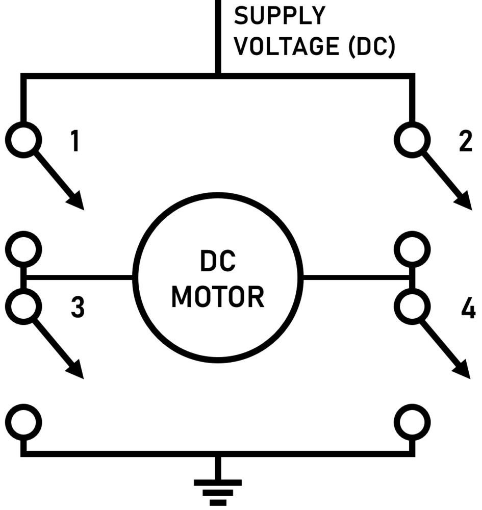
One of the simplest methods for controlling a DC motor is an H bridge circuit. Figure 1 underneath shows a worked on circuit chart of the H Extension:
A schematic illustration of a DC motor control H bridge circuit.
Image 1: DC motor direction control through an H bridge circuit.
When either pair of the four pairs of switches (1, 4, 2, and 3) is closed, the circuit is completed and the motor is powered. Therefore, a four-quadrant motor can be created by combining a few switches whose varying polarities have distinct effects on the motor. In essence, this circuit is reversing the DC motor’s leads, causing it to rotate in the opposite direction upon command. Because the H Bridge can be scaled down with transistors to very small sizes, they are readily available as chips and can be found in the majority of controllers based on microprocessors.
H bridges can be used to control speed in addition to reversing the motor’s direction. The H bridge will be used as a so-called non-regenerative DC drive if only directional control is needed. Regenerative DC drives, on the other hand, can be made with even more complexity. A graph depicting the operation of regenerative drives is shown
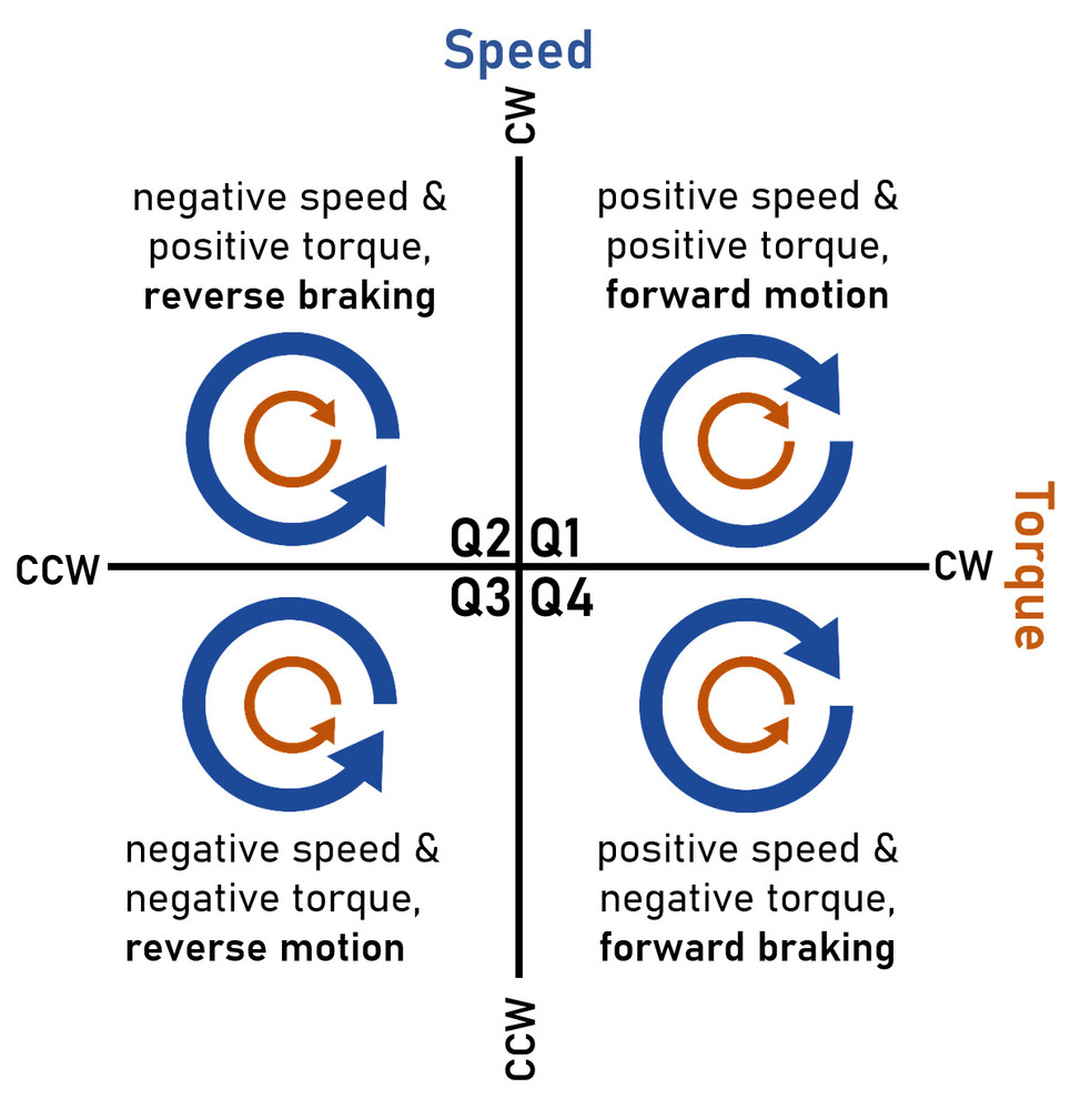
Diagram 3: circuit diagrams depicting the magnitudes of the motor and supply voltages for each quadrant. In quadrants 2 and 4, take note of how the current direction (Ia) changes from the motor to the supply source.
Current will flow back into the power source when the motor slows down because Ea, or the voltage produced or used by the motor, is higher than the supply voltage (Va). The use of regenerative braking in electric vehicles and other applications that need to be as efficient as possible is currently the subject of research. In addition to creating DC motor control, this approach also offers a clever means of reducing power consumption.
Speed Controller: Pulse Width Modulation (PWM)
As demonstrated in our article on AC motor controllers, PWM can be utilized in a variety of motor types. PWM circuits basically alter motor speed by emulating a decrease or increase in supply voltage. Flexible speed drive regulators send occasional heartbeats to the engine, which, when joined with the smoothing impact brought about by curl inductance, makes the engine go about as though it is being fueled by a lower/higher voltage. For instance, if a 12 V motor receives a PWM signal that is high (12 V) for two-thirds of each period and low (0 V) for the remainder, the motor will effectively operate at eight volts, or two-thirds of its full voltage. This will result in a change in the motor’s speed, which is known as the “duty cycle” of the PWM signal. Implementing PWM is simple and inexpensive, and almost any duty cycle is possible, allowing for nearly continuous motor speed control. H bridges and PWM are frequently used together to control both braking and speed.
Armature Controller: Variable resistance
Altering the current that flows through either the armature or the field coil is another method for influencing the speed of a DC motor. Because the speed of the output shaft is proportional to the strength of the armature’s magnetic field (as dictated by the current), any change in the current that flows through these coils will result in a change in the output shaft’s speed. Altering the current and, consequently, speed can be accomplished by connecting these coils to variable resistors or rheostats. By regulating resistance, users can either decrease speed by increasing the stator resistance or increase the armature coil resistance. PWM is the preferred type of DC motor controller because increasing resistance results in losing more energy to heat, which is why this method introduces inefficiency into a motor.
Criteria for Selection and Applications
There are a few important questions you should ask your research or the supplier before making a purchase of a DC motor controller. Due to their diversity, DC motor controllers can be difficult to specify; therefore, the question list provided below will serve as a useful tool for selecting one for your project. By contacting your supplier, ensure that you get the most recent information about the most recent technology that is available, and use these questions to make informed choices:
What parts of the motor’s rated voltage range will it be using, and what is its range?
Which type of control is most desirable—speed, torque, direction, or a combination of the three?
Which kind of motor is being managed?
What is the controller’s maximum continuous current, and does it match the motor’s load-dependent continuous current consumption?
Is there built-in protection against overheating or overcurrent?
What kind of control strategy—PWM, R/C, analog voltage, etc.—will be utilized when employing microprocessor drives? Is software required?
Do you require a controller with two motors (one controller for each motor)?
DC motor controllers are as numerous as the DC motors themselves; One of their greatest benefits is their adaptability. Their applications are additionally as various, as most architects benefit from some sort of client contribution to their DC engine. DC motor controllers are utilized with great success in a variety of applications, including automobiles, manufacturing, robotics, military applications, and more. DC motor controllers can provide a cost-effective, easy-to-use method of control with good precision depending on their application.