


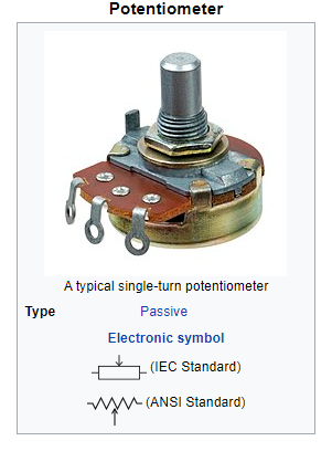
A potentiometer is a resistor with three terminals and a sliding or rotating contact that acts as an adjustable voltage divider.[1] If only two terminals are used, one end and the wiper, it functions as a variable resistor or rheostat.
A potentiometer is a type of measuring device that divides voltage to measure electric potential (voltage); The component’s name comes from the fact that it is an application of the same idea.
Potentiometers are frequently used to control electrical devices like audio equipment volume controls. In a joystick, for instance, potentiometers that are controlled by a mechanism can serve as position transducers. Potentiometers are seldom used to straightforwardly control huge power (in excess of a watt), since the power disseminated in the potentiometer would be tantamount to the power in the controlled burden.
Nomenclature
In the electronics industry, there are a few terms used to describe specific kinds of potentiometers:
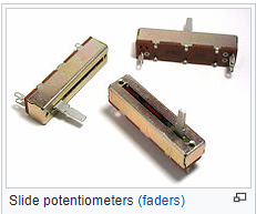
pot with a slide or a slider: a potentiometer that is adjusted by swiping the wiper left or right (or up and down, depending on the installation), typically using a thumb or finger thumb pot, thumbwheel pot, or both: a tiny thumbwheel trimpot or trimmer pot with a small rotating potentiometer for occasional adjustments: a trimmer potentiometer is typically intended for “fine-tuning” an electrical signal by adjusting it once or infrequently.
Construction
Potentiometers comprise of a resistive component, a sliding contact (wiper) that moves along the component, connecting with one piece of it, electrical terminals at each finish of the component, a system that moves the wiper from one finish to the next, and a lodging containing the component and wiper.
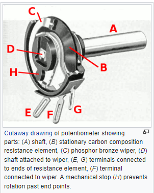
A resistive element (B in the cutaway drawing) is used in the construction of many inexpensive potentiometers. This element is formed into an arc of a circle, usually less than a full turn, and a wiper (C) slides on this element when it is rotated, making electrical contact. The resistive component can be level or calculated. A terminal (E, G) on the case is connected to each end of the resistive element. A third terminal (F), typically located in between the other two, is where the wiper is attached. The wiper is typically the center terminal of three panel potentiometers. This wiper typically travels just under one revolution around the contact for single-turn potentiometers. The confined space that exists between the shaft and the housing in which it rotates is the only entry point for contamination.
The linear slider potentiometer is another type with a wiper that slides along a linear element rather than rotating. Anywhere along the slot that the slider moves in, contamination could potentially enter, making effective sealing more difficult and jeopardizing long-term reliability. The slider position provides a visual indication of the slider potentiometer’s setting, which is an advantage. An array of sliders, such as in a graphic equalizer or the faders on a mixing console, can provide a visual impression of settings, whereas the position of a marking on a rotary potentiometer can be seen.
The resistive component of reasonable potentiometers is frequently made of graphite. Resistance wire, carbon-containing plastic particles, and a ceramic-metal mixture known as cermet are among the other materials utilized. Conductive polymer resistor pastes are used in conductive track potentiometers. In addition to the carbon that provides the conductive properties, these pastes also contain solvents, lubricant, and tough resins and polymers.
Electronic symbol for pre-set potentiometer Multiturn potentiometers are also operated by rotating a shaft, but by several turns rather than less than a full turn. PCB mount trimmer potentiometers, or “trimpots,” are intended for infrequent adjustment. A linear resistive element in some multiturn potentiometers has a lead screw-moved sliding contact; Others have a wiper with a resistive element that is helical and moves along the helix as it rotates for 10, 20, or more complete revolutions. Finer adjustments are possible with preset and user-accessible multiturn potentiometers; The setting is typically altered by one tenth as much when rotated at the same angle as a standard rotary potentiometer.
A string potentiometer is a multi-turn potentiometer that can change linear position into variable resistance by having an attached reel of wire turn against a spring.
A switch that typically operates at the anti-clockwise end of the rotation can be fitted to rotary potentiometers that are accessible to the user. This kind of component was used before digital electronics became the norm to enable equipment like radio and television receivers to be turned on at a low volume with an audible click, then turned up by turning a knob. In stereo audio amplifiers, for instance, multiple resistance elements can be grouped together with their sliding contacts on the same shaft for volume control. When the potentiometer is set at its current position in other applications, such as home light dimmers, the normal usage pattern is best satisfied, so the switch is operated by pushing the knob axially on and off alternately.
Others are contained within the equipment and are meant to be adjusted in order to calibrate it during manufacturing or repair; they should not be touched in any other way. They may require a screwdriver rather than a knob to operate and are typically much smaller than potentiometers that can be accessed by a user. They are typically referred to as “trim[ming] pots” or “preset potentiometers.” To facilitate servicing without disassembling the unit, a small screwdriver inserted through a hole in the case can be used to access some presets.
Resistance–position relationship: “taper”
The manufacturer has control over the “taper” or “law” relationship between slider position and resistance. Any relationship is theoretically possible, but linear or logarithmic (also known as “audio taper”) potentiometers are sufficient for most applications.
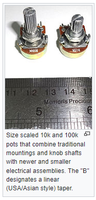
It is possible to identify the type of taper by using a letter code; however, the definitions of the letter codes are not standardized. An “A” for logarithmic taper and a “B” for linear taper are typical markings on potentiometers made in Asia and the United States; C,” which stands for the elusive reverse logarithmic taper. Others, particularly those from Europe, may be identified by displaying an “A” for linear taper, a “C” or “B” for logarithmic taper, or an “F” for reverse logarithmic taper.[2] The code that is utilized likewise varies among the various manufacturers. The resistance value at the midpoint of the shaft rotation is referred to when a percentage is referenced with a non-linear taper. Therefore, at the midpoint of the rotation, a 10% log taper would measure 10% of the total resistance; For instance, a 10 kOhm potentiometer with a 10% log taper would produce 1 kOhm at the midpoint. The log curve gets steeper the higher the percentage.
Linear taper potentiometer
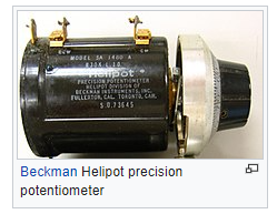
A resistive element with a constant cross-section is used in a linear taper potentiometer, where the resistance between the contact (wiper) and one end terminal is proportional to the distance between them (linear refers to the electrical characteristic of the device, not the geometry of the resistive element). When the division ratio of the potentiometer must be proportional to the angle of shaft rotation (or slider position), such as controls for adjusting the centering of the display on an analog cathode-ray oscilloscope, linear taper potentiometers[4] are used. The relationship between resistance and slider position is precise in precision potentiometers.
Logarithmic potentiometer
A potentiometer with a bias embedded in the resistive element is known as a logarithmic taper potentiometer. This basically indicates that the potentiometer’s center position is not equal to half of its total value. The resistive component is intended to follow a logarithmic shape, otherwise known as a numerical type or “squared” profile. A logarithmic shape potentiometer is built with a resistive component that by the same token “tightens” in from one finish to the next, or is produced using a material whose resistivity changes from one finish to the next. As a result, the device’s output voltage is inversely proportional to the slider position.
The majority of cheaper “log” potentiometers approximate a logarithmic law by using two regions of different resistance but constant resistivity. At approximately half of the way through the potentiometer’s rotation, the two resistive tracks meet; This produces a stepwise logarithmic taper.[5] A linear potentiometer and an external resistor can also be used to simulate a logarithmic potentiometer, albeit less accurately. The cost of a true logarithmic potentiometer is significantly higher.
According to the Weber–Fechner law, the human perception of audio volume is logarithmic, which is why logarithmic taper potentiometers are frequently utilized in audio systems for signal level or volume control.
Contactless potentiometer
Non-contact potentiometers, in contrast to mechanical potentiometers, use an optical disk to activate an infrared sensor or a magnet to activate a magnetic sensor. After that, an electronic circuit processes the signal to produce an analog or digital output signal. Other types of non-contact potentiometers, such as capacitive ones, are possible.
The AS5600 integrated circuit contains an example of a non-contact potentiometer. Absolute encoders, on the other hand, must adhere to the same principles, even though their price must be prohibitive for use in household appliances because they are intended for industrial use.
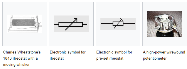
Rheostat
Using a rheostat, which essentially alters the length of a circuit to alter the magnitude of the current, is the most common method for continuously varying the resistance in that circuit[6]. The term “rheostat,” which refers to a two-terminal variable resistor, was coined by Sir Charles Wheatstone around 1845. It is derived from the Greek words “rheos,” which means “stream,” and “states,” which means “setter, regulating device,” from “histanai,” which means “to set, to cause to stand.” A three-terminal potentiometer with one terminal disconnected or connected to the wiper is frequently utilized for low-power applications (less than about 1 watt).
The rheostat can be constructed with a resistance wire wound around a semicircular insulator, with the wiper sliding from one turn of the wire to the next, if the rheostat needs to be rated for more power (more than about 1 watt). A rheostat may be constructed from resistance wire wound on a heat-resistant cylinder. The slider is made of a number of metal fingers that lightly grip onto a small portion of the resistance wire turns. A sliding knob allows the “fingers” to be moved along the resistance wire’s coil, thereby altering the “tapping” point. Applications like DC motor drives, electric welding controls, and generator controls make use of wire-wound rheostats with ratings of up to several thousand watts. The rheostat’s rating is based on its full resistance, and the amount of power that can be lost is proportional to how much of the device’s total resistance is in the circuit. For the purpose of testing power supplies and automobile batteries, carbon-pile rheostats are used as load banks.
Digital potentiometer
An electronic component that replicates the functions of analog potentiometers is referred to as a digital potentiometer, or digipot. Similar to an analog potentiometer, the resistance between two terminals can be changed using digital input signals. There are two main categories of functions: non-volatile, which retain their set position using a storage mechanism similar to flash memory or EEPROM, and volatile, which lose their set position if power is removed and are typically designed to initialize at the minimum position.
A digipot’s use is significantly more complicated than that of a straightforward mechanical potentiometer, and there are numerous restrictions to be observed; in any case they are generally utilized, frequently for processing plant change and alignment of hardware, particularly where the impediments of mechanical potentiometers are dangerous. A digipot is for the most part safe with the impacts of moderate long haul mechanical vibration or natural pollution, in a similar way as other semiconductor gadgets, and can be gotten electronically against unapproved altering by safeguarding the admittance to its customizing inputs by different means.
A multiplying DAC can be used in place of a digipot in equipment that has a microprocessor, FPGA, or other functional logic that can store settings and reload them to the “potentiometer” every time the equipment is powered on. This can offer higher setting resolution, less temperature drift, and more operational flexibility.
Membrane potentiometers
A membrane potentiometer connects a resistor voltage divider to a conductive membrane that has been deformed by a sliding element. Depending on the material, design, and manufacturing procedure, linearity can range anywhere from 0.50% to 5%. With a theoretically infinite resolution, the repeat accuracy typically ranges from 0.1 mm to 1.0 mm. Depending on the actuation method and the materials used in the manufacturing process, these kinds of potentiometers typically have a service life of one million to twenty million cycles. (To sense position), there are contact and contactless (magnetic) methods available. PET, FR4, and Kapton are just a few of the many available materials. Manufacturers of membrane potentiometers offer linear, rotary, and application-specific variants. The linear versions can have a length of anywhere from 9 mm to 1000 mm, and the rotary versions can have a diameter anywhere from 20 mm to 450 mm and a height of 0.5 mm. Position sensing can be accomplished with membrane potentiometers.[10] A two-dimensional membrane potentiometer provides x and y coordinates for resistive touch-screen devices. The top layer is meager glass separated near an adjoining internal layer. The top layer has a transparent conductive coating on its underside; A transparent resistive coating covers the surface of the layer that lies beneath it. The glass is deformed by a stylus or finger to make contact with the underneath layer. Conductive contacts are located at the resistive layer’s edges. Applying voltage to opposite edges while temporarily disconnecting the remaining two edges is how the contact point is found. One coordinate is provided by the voltage of the top layer. The other coordinate is obtained by severing those two edges and applying voltage to the other two, which were never connected before. Position updates are provided frequently by rapidly switching between pairs of edges. Output data is provided by a converter from analog to digital.
The fact that these sensors only require five connections and that the electronics that go with them are relatively simple are two of their advantages. Another thing that works well is any material that presses down on the top layer in a small area. The fact that sufficient force is required to make contact is a drawback. Another issue is that the sensor needs to be calibrated on occasion in order to match the touch location to the display underneath. Only the proximity of a finger or other conductive object is required for capacitive sensors, which do not require calibration or a forceful contact. They are, however, significantly more complicated.
Applications
Most of the time, potentiometers aren’t used to directly control much power (more than a watt). Instead, they are used as control inputs for electronic circuits and to adjust the level of analog signals (such as audio equipment volume controls). A light dimmer, for instance, indirectly controls the brightness of lamps by using a potentiometer to control the switching of a TRIAC.
In the electronics industry, where adjustments must be made during manufacturing or maintenance, preset potentiometers are frequently used.
Potentiometers that are activated by the user can be used as user controls to control a wide range of equipment functions. Potentiometers became less common in consumer electronics in the 1990s, making way for rotary incremental encoders, up/down pushbuttons, and other digital controls. However, they continue to be used in numerous applications, including as position sensors and volume controls.
Audio control
Slide and rotary low-power potentiometers are used to adjust the loudness, frequency attenuation, and other characteristics of audio signals in audio equipment.
The ‘log pot’, that is, a potentiometer has an opposition, tighten, or, “bend” (or law) of a logarithmic (log) structure, is utilized as the volume control in sound power enhancers, where it is likewise called an “sound shape pot”, on the grounds that the plentifulness reaction of the human ear is roughly logarithmic. It ensures that, for instance, a setting of 5 on a volume control marked from 0 to 10 sounds subjectively half as loud as a setting of 10. An anti-log pot, also known as a reverse audio taper, is merely the opposite of a logarithmic potentiometer. It is almost always utilized in an audio balance control, for instance, in a ganged configuration with a logarithmic potentiometer.
When combined with filter networks, potentiometers function as equalizers or tone controls.
Due to the straight-line nature of the physical sliding motion, the term “linear” is sometimes used in audio systems in a confutative manner to describe slide potentiometers. When applied to a potentiometer, whether it is a slide or rotary model, the term “linear” refers to a linear relationship between the pot’s position and the measured value of its tap (wiper or electrical output) pin.
Television
In the past, potentiometers were used to control the brightness, contrast, and color response of a picture. Adjusting “vertical hold,” which affected the synchronization between the internal sweep circuit (sometimes a multivibrator) of the receiver and the received picture signal, as well as other factors like audio-video carrier offset, tuning frequency (for push-button sets), and so on, was frequently done with a potentiometer. Additionally, it aids in wave frequency modulation.
Motion control
In a servomechanism, potentiometers can be used as position feedback devices to create closed-loop control. The simplest method of measuring the angle or displacement is this motion control method.
Transducers
Potentiometers are also very widely used as a part of displacement transducers because of the simplicity of construction and because they can give a large output signal.
Computation
High precision potentiometers are used in analog computers to set initial conditions for a calculation or to scale intermediate results by desired constant factors. A motor-driven potentiometer can be used as a function generator, providing approximations of trigonometric functions via a non-linear resistance card. The voltage division ratio can be made to be proportional to the cosine of an angle by using the shaft rotation as an example.
Theory of operation
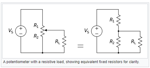
From a fixed input voltage applied across the two ends of the potentiometer, a voltage divider can be used to produce a manually adjustable output voltage at the slider (wiper). They are most often used in this way.
The formula for determining the voltage across RL is:
{\displaystyle V_{\mathrm {L} }={R_{2}R_{\mathrm {L} } \over R_{1}R_{\mathrm {L} }+R_{2}R_{\mathrm {L} }+R_{1}R_{2}}\cdot V_{s}.}{\displaystyle V_{\mathrm {L} }={R_{2}R_{\mathrm {L} } \over R_{1}R_{\mathrm {L} }+R_{2}R_{\mathrm {L} }+R_{1}R_{2}}\cdot V_{s}.}
The simpler equation can be used to approximate the output voltage if RL is large in comparison to the other resistances (such as the input to an operational amplifier):
Displaystyle V_mathrm L is equal to R_2 over R_1+R_2 cdot V_s. Displaystyle V_mathrm L is equal to R_2 over R_1+R_2 cdot V_s.
(dividing everything by RL and canceling terms with RL as the denominator) As an illustration, consider the following: “displaystyle V_mathrm S=10mathrm V”; “displaystyle V_mathrm S=10”; “displaystyle V_mathrm S=10”; “displaystyle V_mathrm S=10
The output voltage VL will approximate: due to the large load resistance in comparison to the other resistances.
Displaystyle: 2 math k Omega over 1 math k Omega +2 math k Omega cdot 10 math V = 2 over 3 math k Omega approx 6.667 math V. Displaystyle: 2 math k Omega over 1 math k Omega +2 math k Omega cdot 10 math V = 2 over 3 math k Omega approx 6.667 math V.
However, due to the load resistance, it will actually be somewhat lower: ≈ 6.623 V.
One of the benefits of the potential divider contrasted with a variable resistor in series with the source is that, while variable resistors have a greatest obstruction where some ongoing will continuously stream, dividers can differ the result voltage from most extreme (Versus) to ground (zero volts) as the wiper moves from one finish of the potentiometer to the next. However, there is always a small amount of resistance to contact.
Additionally, the load resistance is frequently unknown, so simply connecting a variable resistor to the load in series could have a negligible or excessive effect on the load, depending on the load.