


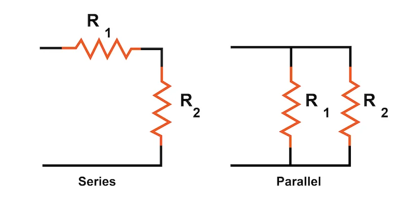
To create a single path for the flow of current, each component in a series circuit is connected from beginning to end. With exactly two electrically common nodes and the same voltage across each component, all components in a parallel circuit are connected to one another.
Analyzing circuits with only one battery and one load resistance is easy, but they are rarely used in real-world situations. Most of the time, we find circuits in which more than two parts are connected to each other
Connecting more than two circuit components can be done in two primary ways: parallel and series Series-parallel circuits that are more intricate can be made by combining these two fundamental connection techniques.
What is a Series Connection?
A series circuit is one in which the components are connected in a line from end to end, as shown in Figure 1.
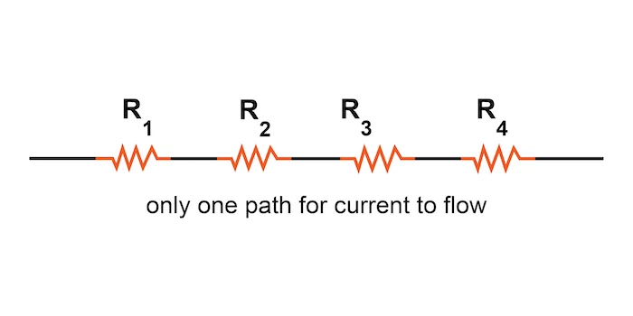
Figure 1 shows the series connection of resistors. Resistors connected in series These series resistors provide a single path for the flow of current.
An Example of a Series Circuit: An Introduction to Series Circuits
A Series Circuit Example: An Overview of Series Circuits
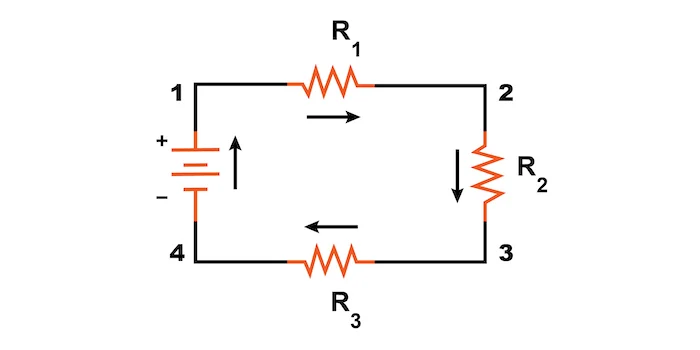
Three resistors, designated R1, R2, and R3, are connected in a long chain from one terminal of the battery to the other in this case. In a series circuit, each resistor and its closest neighbor share a single electrical node.
Note: The resistor values in ohms have no bearing on the subscript labels—those small numbers to the right of the letter “R.” They are only used to differentiate between resistors.
The fact that every component in a series circuit receives the same amount of current is the defining feature of a series circuit. The current can only move in one direction. In the circuit depicted in Figure 2, the current (I) travels in a clockwise direction to complete a complete loop from the positive battery terminal back to the negative battery terminal. From there, it travels through the battery in the order 1–2–3–4–1.
What is meant by a parallel connection?
A parallel circuit is one in which all of the components are connected across the leads of each other, as shown in Figure 3.
An illustration of resistors connected in parallel.
- Figure An illustration of resistors connected in parallel.
No matter how many components are connected in a purely parallel circuit, there will never be more than two sets of electrically common points. While there are numerous paths for the flow of current, there is only one voltage across all components.
An Overview of Parallel Circuits and an Illustration of a Parallel Circuit
Let’s take a look at an illustration of a parallel circuit in Figure 4.
An illustration of a parallel circuit
- Figure An illustration of a parallel circuit
We have three resistors once more, but this time there are three loops for the current to return to the negative terminal from the positive battery terminal
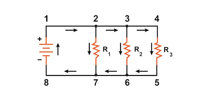
1-2-7-8-1
1-2-3-6-7-8-1
1-2-3-4-5-6-7-8-1
Every individual way through R1, R2, and R3 (2-7, 3-6, and 4-5) is known as a branch.
An equal circuit’s characterizing trademark is that all parts are associated between similar arrangement of electrically normal places. The points 1, 2, 3, and 4 on the schematic depicted in Figure 4 are all electrically common; Points 5, 6, 7, and 8 also apply. Between these two sets of points, the battery and all of the resistors are connected. This indicates that all components in a parallel circuit lose the same voltage (V).
Comparing Parallel and Series Circuits:
Every component in a series circuit is connected from end to end, creating a single path for the flow of current.
All components are connected across one another in a parallel circuit, resulting in precisely two sets of electrically common points.
A path that one of the load components, like a resistor, creates for electric current is known as a “branch” in a parallel circuit.