Objectives:
Study on fundamentals of BLDC motor
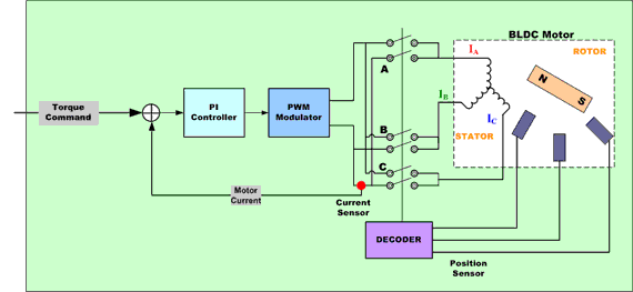
Role of DC converter in BLDC motor controller
Inverter switching and control logic
Commutation Logic and Controller operation
Introduction:
BLDC motors overcome the shortcomings of brushed motors by replacing
mechanical commutation with electronic commutation. To better understand
this, it is useful to take a closer look at the BLDC motor structure.
A BLDC motor is a kind of flipped version of a brushed motor because the
permanent magnets are installed in the rotor, whereas the coil windings become
the stator.
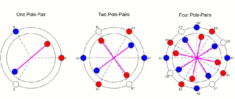
There are motors with different magnet arrangements where the stator may have
different numbers of windings and the rotor may have multiple pole pairs as can
be seen in the following images.
BLDC motors and PMSMs are similarly structured where both have permanent
magnets in the rotor and are defined as synchronous motors. In a synchronous
motor, the rotor is synchronized with the stator magnetic field, i.e., the rotor
turns at the same speed as the stator magnetic field.
Their key difference is the shape of their back EMF (electromotive force).
When electrical motors are rotated, they act as generators. In other words, a
voltage is induced in the stator that opposes the driving voltage of the motor.
Back EMF is an important characteristic of a motor as its shape dictates the kind
of algorithm required to optimally control it.
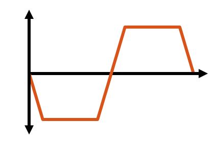
Due to their design, BLDC motors have a trapezoidal back EMF shape and are
commonly controlled by trapezoidal commutation.
BLDC
Trapezoidal Back EMF
Controlled by trapezoidal commutation
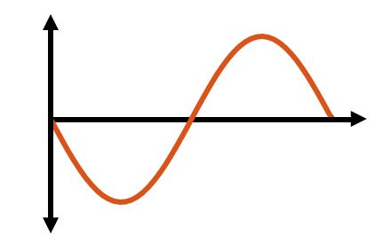
PMSMs are controlled by field-oriented control because their back EMF has a
sinusoidal shape.
PMSM
Sinusoidal Back EMF
Controlled by field-oriented control
Sometimes the terms PMSM and BLDC are used interchangeably among the
motor control community, which may cause confusion about their back EMF
profiles. For this discussion, BLDC motors will strictly be machines with
trapezoidal back EMF.
MATLAB simulation steps:
Simulate back-EMF voltage of a BLDC motor
Modeling a three-phase inverter
Modeling commutation logic
Modeling a PWM-controlled buck converter
PWM Control of a BLDC motor
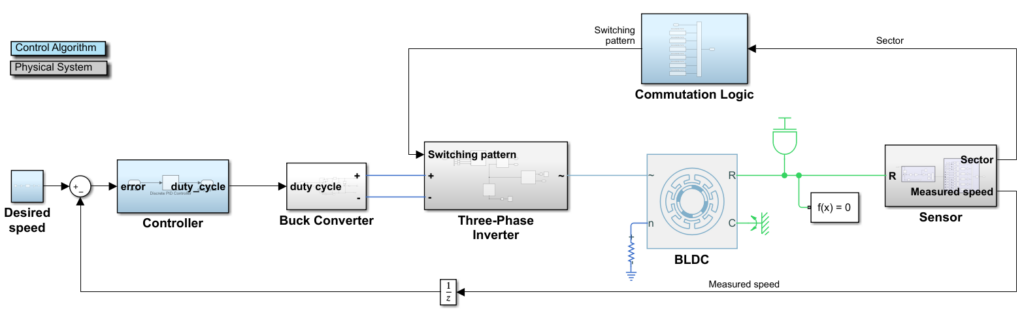
SIMULINK model:
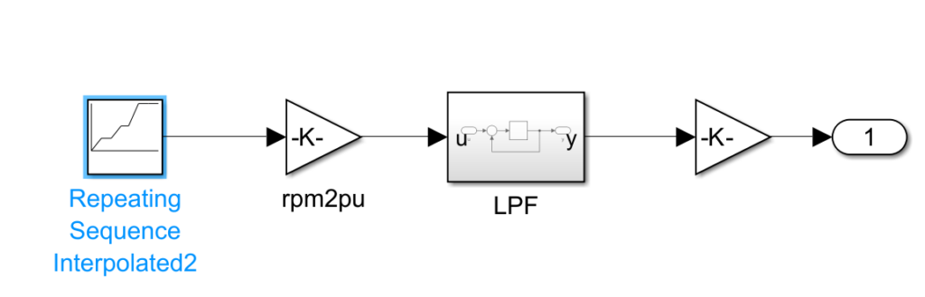
Desired speed subsystem:
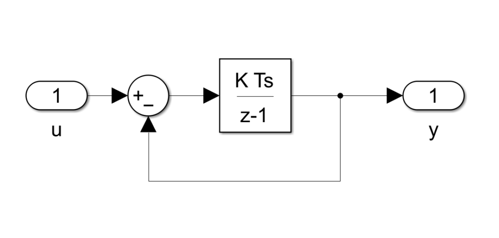
LFP subsystem:
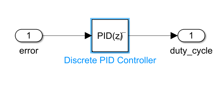
Controller Subsystem:
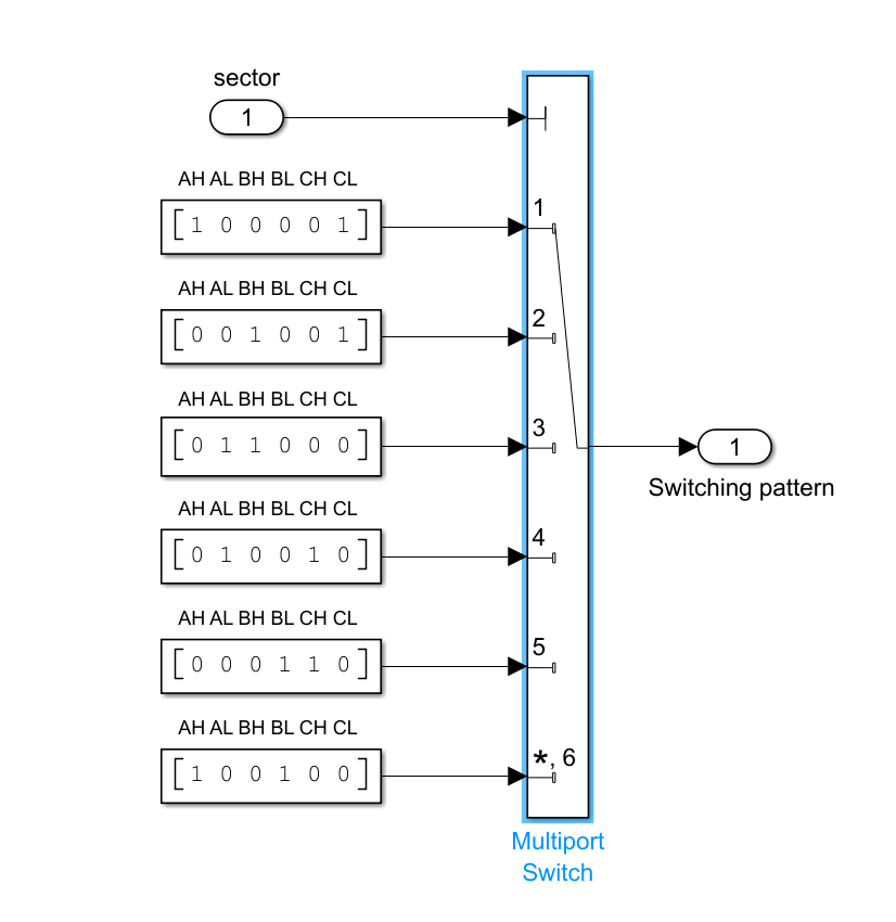
Commutation Logic subsystem:
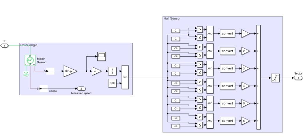
Sensors Subsystems
Results:
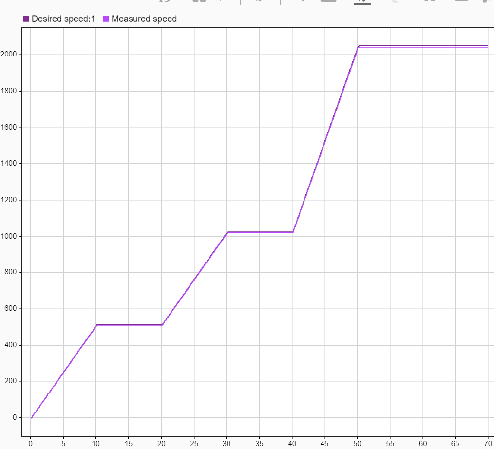
Conclusion:
Successfully developed the model for the BLDC motor speed controller. It has
been analysed that the desired speed is overlapped with the measured speed that
shows the right selection of the parameters and commutation logics.