


Due to its frequency-dependent impedance, the capacitor is a reactive component utilized in analog electronic filters. Frequency can affect the signal-affecting capacitor. Therefore, this property is extensively utilized in filter design. A predefined signal processing function can be carried out with the help of analog electronic filters like LPF. This filter’s primary function is to allow low frequencies while preventing high frequencies. In a similar manner, an HPF permits high frequencies while preventing low frequencies. Analog components like resistors, capacitors, transistors, op-amps, and inductors can be used to construct the electronic filter. The filter capacitor and how it works are covered in this article.
What is a Filter Capacitor?
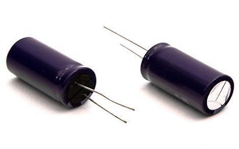
The filter capacitor is a type of capacitor that is used to remove a particular frequency or series of frequencies from an electronic circuit. By and large, a capacitor sift through the signs which have a low recurrence. These signals are also known as DC signals because their frequency value is close to 0 Hz. Therefore, this capacitor is utilized for frequency filtering. These are utilized in a variety of contexts and are extremely prevalent in electrical and electronic equipment.
Working of Filter Capacitor
The capacitive reactance principle is largely responsible for this capacitor’s operation. It is only how the impedance of a capacitor modifies with a sign recurrence that is moving through it. Except for the signal’s frequency, a nonreactive component like a resistor provides a similar resistance to a signal. This indicates that the resistance of a resistor is the same for signals at 1 Hz and 100 kHz.
The impedance or resistance of a capacitor, on the other hand, varies with the signal frequency passing through it. Utilizing a formula such as XC= 1/2 fc, these reactive devices provide low-frequency signals with high resistance and high-frequency signals with low resistance. A capacitor gives disparate impedance values for divergent recurrence signal. It can act as a resistor in a circuit.
Formula for the Filter Capacitor In power supply circuits, this capacitor can be calculated to minimize output ripple. The formula is C = I / 2f Vpp. As can be seen from the previous equation, “I” denotes the load current, “f” denotes the i/p frequency of the AC, and “Vpp” denotes the minimum ripple that may be considered acceptable due to the fact that it is virtually impossible to achieve a “0” PCBWay Filter Capacitor Circuit The capacitor acts as a high pass filter in this circuit, allowing high frequencies while preventing direct current. In a similar vein, they can be utilized as a low pass filter to permit DC and prevent AC.
Here the capacitor is associated in lined up with the part as opposed to associating in series. A high-frequency capacitive filter is used in this circuit. The current will flow in the direction with the least resistance in this location.
Filter Capacitor Circuit Filter Capacitor Circuit High-frequency signals will flow through a capacitor because a capacitor has a very low resistance. Like this, the circuit in this game plan, it is a high-recurrence channel. Because the capacitor has a high resistance for low-frequency signals, signals like low-frequency current won’t flow through it.
Filter Capacitor Circuit to Pass AC and Block DC For signals with a low frequency, the capacitor has a very high resistance, while for signals with a high frequency, it has a lower resistance. As a result, it serves as a high pass filter, allowing high-frequency signals to pass through while preventing low-frequency signals from doing so.
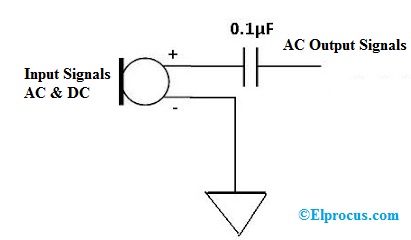
Circuit to Block DC and Pass AC In a circuit, both AC and DC signals can be used multiple times. However, there are times when we only require AC signals, so the DC signals will be removed. A circuit for a microphone is the best illustration of this. DC is supplied to the microphone as an input in this situation. We want DC as contribution to the receiver to turn on and we require AC as contribution to address the music, voice signals, and so on
Sift Through the DC Part from the Sign
A capacitor is utilized to sift through the DC signal. By connecting the capacitor to the circuit in series, this can be accomplished. The capacitive high-pass filter can be found in the next circuit. DC and low frequency signals will be blocked by this.
In most cases, a ceramic capacitor with a value of 0.1 F can be positioned following the signal, which can be either an AC or DC signal. This capacitor removes the DC component while allowing for AC.
Applications of a filter capacitor include the ones listed below.
The line filter capacitor is used in a variety of industrial loads and appliances to shield the appliance from line voltage noise and protect other devices on a similar line from the circuit’s generated noise.
All kinds of signal processing filters can make use of these capacitors. The best application of this program is something like an audio equalizer. It amplifies low, high, and midrange frequencies through the use of various frequency bands.
It is used to remove glitches from DC power rails. It is also used to remove radio frequency interference (RFI) from equipment that uses power or signal lines to enter or exit.
For a smooth DC power supply, this capacitor can be connected after the voltage regulator.
Audio, IF, and RF filters all make use of this capacitor (FAQ 1). What is a filter capacitor used for?
A variety of frequencies can be removed from a circuit using this method.
2) How is the capacitor filtered?
A capacitor is used to filter the pulsating DC o/p once rectification in a power supply to supply a nearly stable DC voltage to the load.
3). What are the capacitor filter’s limitations?
The filtering and voltage regulation are subpar.
4). What is the distinction among sidestep and decoupling capacitor?
The noise signals are pushed by the bypass capacitor, while the distorted signal is stabilized by the decoupling capacitor to smooth the signal.
Hence, this is about an outline of channel capacitor, working, equation, circuits, and its applications. I have a question for you: what is a filter capacitor’s primary function?
SHARE THIS Article: