


The Liquid Crystal Display modules play a crucial role in the design of embedded systems based on Arduino. As a result, learning how to interface an LCD with an Arduino 162 is crucial to embedded system design. Communication between the human world and the machine world relies heavily on display units. The display unit functions in the same way regardless of the size of the display—it can be large or small. We are utilizing straightforward displays such as 161 and 162 units. 16 characters are displayed on a single line in the 16-1 display unit, while 32 characters are displayed on the 16-2 display unit. We should be aware that there are 510 pixels needed to display each character. Therefore, all 50 pixels should be aligned to display a single character. The controller in the display, HD44780, is used to control the characters’ pixels on the screen.
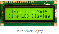
What is a Liquid Crystal Display?
Although they do not directly emit light, liquid crystal displays use the liquid crystal’s light monitoring property. Electronic visual display (EVD) or flat panel display is the liquid crystal display. With uninformed, content the LCD’ s are acquired in the proper picture or the erratic picture which are shown or secret like present words, digits, or 7 portion show. The element has larger elements, and the arbitrary images are composed of a large number of small pixels.
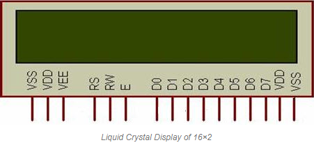
Liquid Crystal Display of 16×2
The two horizontal lines that make up the 162 liquid crystal display are used to compress the space between the characters. The LCD has two registers built in, which are outlined below.
Data Register in the Command Register
Command Register: This register is used to insert a special command in the LCD. The command is a special set of data and it is used to give the internal command to the liquid crystal display like clear screen, move to line 1 character 1, setting the curser and etc.
Data Register: The data registers are used to enter the line in the LCD
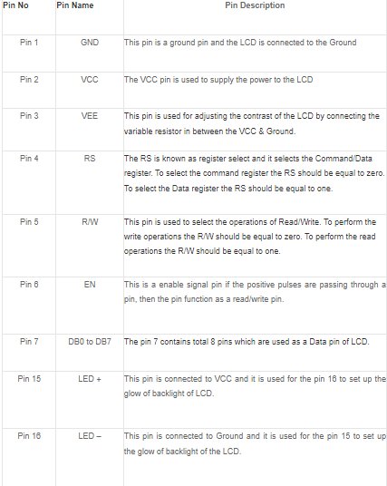
Pin diagram and description of each pin have explained in the following table.
LCD Interfacing with the Arduino Module
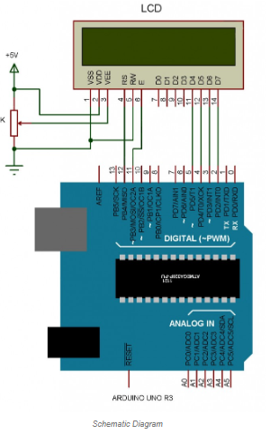
The liquid crystal display with the Arduino module is depicted in the following circuit diagram. We can see from the circuit diagram that the LCD’s RS pin is connected to the Arduino’s pin 12. The ground is connected to the LCD on the R/W pin. The LCD module’s enable signal pin is connected to Arduino pin 11. The LCD module and Arduino module are connected with the 4-bit mode in this venture. As a result, the LCD has four input lines, DB4 to DB7. This procedure is straightforward, requires fewer connection cables, and allows us to maximize the LCD module’s potential.
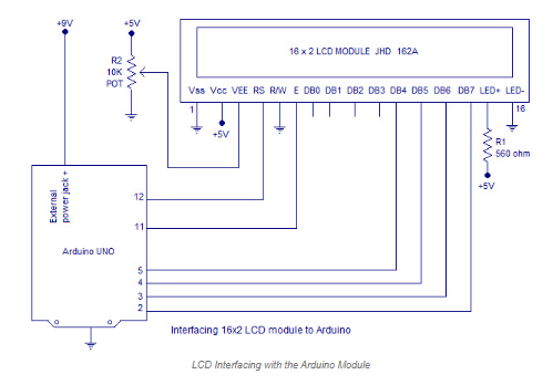
The Arduino pins from 5-2 are connected to the digital input lines (DB4-DB7). A 10K potentiometer is what we are using here to adjust the display’s contrast. The 560-ohm resistor supplies the current that flows through the back LED light. The Arduino is supplied with the external power jack by the board. The Arduino can be powered through the USB port on the PC. A few pieces of the circuit can require the +5V power supply it is taken from the 5V source on the Arduino board.
The LCD module’s connection to the Arduino is depicted in the following schematic diagram.
The LCD module’s interface with the Arduino is explained in this article. I hope you now have a basic understanding of how to use an Arduino LCD module after reading this article. Please don’t hesitate to leave a comment in the section below if you have any questions about this article or the microcontroller projects. The following is a question for you: how does the LCD module interact with the Arduino?