


When learning a new programming language, the first program you typically write is called “Hello World.” The only thing it does is show the words “Hello World” on the computer screen.
The equivalent of “Hello World” when learning to program microcontrollers like the Arduino is a program that blinks an LED. You can guess what it’s called: Blink.
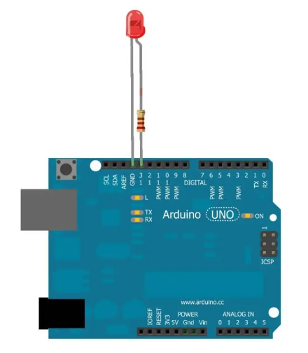
STEP-BY-STEP INSTRUCTIONS
Use the GND pin closest to pin 13 to connect the LED’s short leg to your Arduino.
Associate the 220 Ohm resistor to nail 13 to the Arduino. The resistor can be connected in any direction.
Connect the LED’s long leg to the resistor’s other leg with the alligator clip. To ensure a stable electrical connection, twist the two leads together as best you can if you do not have an alligator clip.
Using a USB cable, connect the Arduino board to your computer.
Navigate to the Arduino IDE.
Open the section’s drawing.
In the upper left, click the Verify button. It ought to change from blue to orange.
Select the “Upload” option. After the sketch has finished uploading to your Arduino board, it will also turn orange and then blue.
Now keep an eye on the Arduino board; the LED ought to be flashing.
DISCUSS THE SKETCH
You can see the Arduino code that makes up the Blink program on the previous page. Read every line, even if it doesn’t make sense at this point.
Pay attention to the comments at the program’s top. It is always a good idea to take the time to listen to what the programmer has to say about the sketch they wrote, as evidenced by the use of the multi-line comments syntax /* */. The comments will probably be brief and will likely explain how the program works or what it should do. Some might even instruct you on how to join the circuit.
The Blink sketch’s subsequent block of code is void setup() // initialize the digital pin as an output.
pinMode; led, OUTPUT
Keep in mind that almost every Arduino sketch contains the setup() function. Code that will only be executed once by the Arduino is contained within the curly braces. For this sketch notice the capability pinMode() is inside the wavy supports of the arrangement() capability.
To begin, let me say that pinMode() is an excellent function. If you recall, arguments can be passed to functions. The pinMode() function requires a pin number and a mode for that pin as its two arguments. The pin numbers are straightforward: A0 to A5 for analog pins and 0 to 13 for digital pins.
The pin should be either an INPUT (good for reading a sensor) or an OUTPUT (good for powering an LED), which is an easy way to identify the mode.
A pin is made ready to read the voltages that will be applied at it when it is set to be an INPUT. A pin is prepared to output voltage when it is set as an OUTPUT; more on this later.
In this example, we want to illuminate an LED, which necessitates applying voltage to pin 13. As a result, we require setting pin 13’s mode as an OUTPUT. Keep in mind that setting the pin’s mode to OUTPUT doesn’t cause a voltage to be applied; rather, it makes it possible for the pin to supply a voltage once it has been programmed to do so.
We come to our favorite and ubiquitous function, void loop(), in the final block of code. digitalWrite(led,HIGH);// turn the LED on (HIGH is the voltage level) delay(1000); // wait a second before performing digitalWrite(led,LOW); // By setting the voltage to LOW delay(1000), the LED will turn off. // Hold on a second—you may be aware that void loop() repeats itself. Two functions are visible within this loop: digitalWrite() and delay().
The capability digitalWrite() is utilized to apply either HIGH or LOW voltage to a pin. The pin you select will receive 5 volts at HIGH, while the pin will receive 0 volts at LOW. Assuming you apply 5 volts to a pin that is associated through a Prompted ground, then, at that point, the Drove will illuminate.
The LED can carry current because there is a voltage difference between the pin and ground. Because the voltages at ground and the pin are both zero, if you apply 0 volts to the same pin, the LED will not light up because no current is being “pushed” through the circuit.
As previously mentioned, the pin number and the voltage level, either HIGH or LOW, are the two arguments passed to digitalWrite().
led, HIGH; // digitalWrite turn on the LED by applying HIGH voltage to pin 13, where our LED is attached, in order to initiate the loop. We use the variable name “led” in the digitalWrite() function to return to the previously assigned value 13.
We can make use of the variable “led” rather than having to explicitly write 13 in the digitalWrite() function. Because they can replace numbers and are much simpler to change and track, variables are fantastic in this way. The Arduino will see 13 each time the “led” variable is used. We only need to change the value of “led” once if we decide later to move our LED to pin 10, and all instances of “led” will also change.
The LED will become bright once the digitalWrite() function is executed; we just applied 5 volts, so that makes sense. The next thing we do is put off writing the Arduino sketch so we can enjoy the LED’s bright light. We use the delay() function to accomplish this.
The number of milliseconds you want the program to delay is the only argument that the delay() function accepts. In this instance, we require one second, or one thousand milliseconds.
After saying “apply high voltage,” we now say “wait a second.” Our LED will only glow for a single instant. But that gets old, and we have to stick to the sketch’s name, so we tell the Arduino to write a LOW voltage to pin 13 using the same digitalWrite() function, but we want a LOW voltage instead of a HIGH voltage.
Now that there is no current flowing, the LED goes dark. We use the delay() function once more for one second to maintain that darkness. The LED is now dim for a split second.
The loop has come to an end for us. We briefly turned on the LED and then turned it off; what came next? The Arduino starts over at the top of the loop once the loop is finished and keeps going like a record.
The LED will light up once more, delay for one second, and then dim for one second. You now have a blinking LED, which is pretty cool for only a few lines of code!.