


Mass Flow Meters
The application of mass flow meters is examined in depth in this article.
You’ll gain more knowledge about things like:
How does a mass flow meter work?
How Does a Mass Stream Meter Work
Kinds of Mass Stream Meters
Mass Stream Meter Kinds of Readings
Furthermore, substantially more…
The first chapter explains mass flow meters.
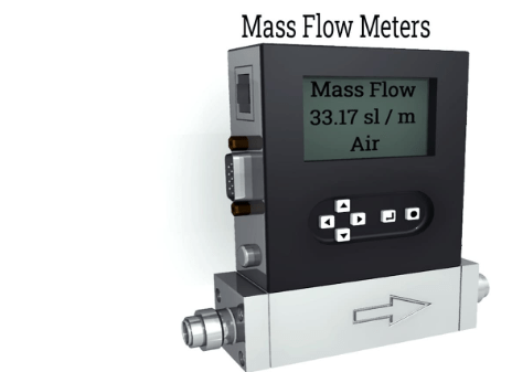
A mass flow meter uses temperature sensors and electric heaters in the flow or outside the pipe to measure the flow rate of a gas based on the convective transfer of heat on the gas’s surface. Mass flow rates of fluids passing through a fixed point in a predetermined amount of time are measured by inertial flow meters.
Depending on the industry in which they are utilized, mass flow meters are referred to as flow gauge, flow indicator, liquid meter, or flow rate sensor. Due to their accuracy and precision, mass flow meters have replaced other methods of measuring flow rates.
Thermal and Coriolis flow technologies are utilized for the purpose of measuring mass flow. The Coriolis effect, which states that a mass moving in a rotating system generates force perpendicular to the motion and rotational axis, is utilized by Coriolis flow meters. To determine mass flow, a Coriolis-meter uses sensors to record the amplitude, frequency, and phase shift of the oscillations caused by a gas passing through oscillating tubes.
Thermal mass flow meters make use of the principles of heat transfer by utilizing temperature sensors and a heating element. As the gas moves through the sensors, it generates thermal energy, which raises its temperature and can be used to calculate the flow rate.
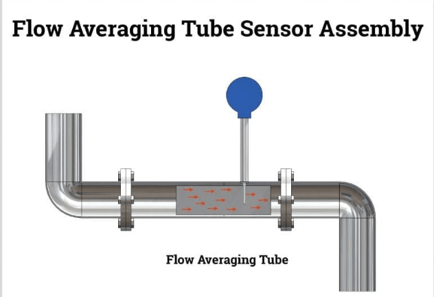
Flow Averaging Tube Sensor Assembly The picture above shows a mass flow meter that is inserted into a pipe to measure the flow rate.
Producers incorporate mounted temperature and strain sensors with a stream sensor. The equation of mass flow equals density multiplied by volume flow multiplied by the area of the flow body, where the area is always dependent on the size of the flow body, is used by the electronics of flow meters to calculate mass flow. The velocity of the flow is measured by a rotating turbine or vortex sensor, and the pressure and temperature of the flow are used to calculate density.
The proportion of stream is a significant piece of controlling interaction conditions for a plant’s creation, effectiveness, and nature of items. Measurements of flow can sometimes serve as indicators of a process’s efficiency.
Part Two – How Does a Mass Stream Meter Work?
Although all mass flow meters use different methods to take measurements, they all measure flow rates. There is no established standard for evaluating flow rates. They differ based on the conditions, the material being measured, and the required accuracy.
In order to maximize operational effectiveness, production facilities require flow meters to provide precise fluid flow readings. Measurements of flow provide indicators of the system’s overall performance.
Mass flow meters’ primary function is to measure variations in flow caused by viscosity and density, which affect flow measurement accuracy. There are many different ways that temperature affects a fluid’s density. Mass flow meters are used to monitor and balance fuels, requiring an accuracy of less than one percent.
A brief explanation of how a few flow meters operate is provided below.
Direct Mass Flow Measurement The physical properties of fluids, such as the difference between mass and volumetric flow, can’t be used to measure mass flow accurately. Mass flow meters are utilized for the primary reason that direct mass flow measurements are absolute measurements that are taken directly from the medium’s flow and are unaffected by changes in pressure, temperature, viscosity, and density.
As long as the conditions and reference calibrations are strictly adhered to, volumetric measuring instruments remain valid. Sadly, volumetric instruments like turbine flow meters or variable area meters cannot detect changes in temperature or pressure that affect the flow rate.
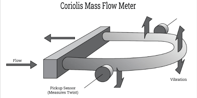
The Coriolis Principle The effect that a moving, rotating mass has on a body is known as the Coriolis principle. The body is deformed by the force of the moving mass, known as the Coriolis force, which appears to deflect the body from its path. The principle behind Coriolis flow meters is that the force acts on the body’s motion rather than directly on the body.
Despite its simplicity, the Coriolis principle is extremely effective. A tube is involved, and a fixed vibration powers it up. A phase shift occurs when a fluid flows through a tube and the mass flow momentum alters the vibration of the tube. A linear output that is proportional to flow is obtained from the phase shift. Any gas or liquid can be measured using the Coriolis method, which works regardless of the material in the tube.
The natural frequency, which changes in direct proportion to the fluid density, can be measured in addition to the phase shift frequency. The volume flow rate can also be calculated using the phase shift’s mass flow rate and density.
Utilizing the Coriolis effect, Coriolis meters measure direct flow. The stream bearing is straight through the meter, taking into consideration higher stream rates and less tension misfortune.
The application of the Coriolis principle is depicted in the straightforward diagram below.
Mass Flow Indirect Measurement
An approach to measuring things using alternative methods or properties is called indirect measurement. When it is not possible to directly measure something, like the height of a building or the distance across a river, they are essential. The Pythagorean theorem, proportions, and geometric shapes are just a few of the many mathematical formulas and calculations that are utilized in the process of carrying out indirect measurement.
Volumetric meters like turbine, magnetic, ultrasonic, differential pressure, positive displacement, variable area, and non-compensated vortex meters can be used with a flow computer to calculate mass flow when combined with pressure and temperature sensors. The use of multiple sensors and computers to measure mass flow makes this type of measurement indirect. The inability of direct mass flow meters to meet the requirements of an application necessitates the use of indirect mass flow measurement.
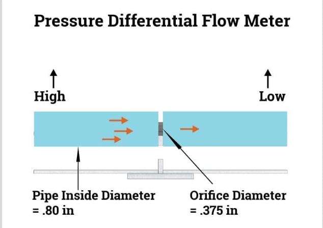
Methods for Differential Pressure (DP)
A type of flow meter known as a DP meter has been in use for more than a century. Bernauli’s law, which states that a difference in pressure causes flow velocity, is utilized. DP pressure flow gauges, which cause a narrowing of the pipe and a decrease in pressure, can be used to calculate the velocity of flow by measuring the value of pressure changes.
By balancing the legs of the bridge circuit, differential pressure meters have four matched orifice plates in a Wheatstone bridge arrangement, or resistance bridge, that calculates the unknown resistance. To establish a reference flow, a pump moves fluid at a predetermined rate from one branch of the bridge to another. The mass flow rate is determined by measuring the differential pressure across the bridge.
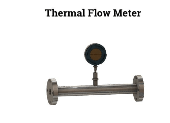
Warm Mass Stream Meter
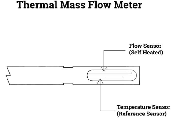
Thermal mass flow meters are precise instruments for directly measuring gas mass flow for a variety of gas types. Using convective heat transfer, a probe is inserted into the gas stream of a pipe, stack, or duct to measure gas flow.
At the tip of a thermal mass flow meter, two resistance temperature detector (RTD) sensors measure heat transfer as a fluid passes over a heated surface. An integrated circuit heats one of the RTDs, while the reference RTD determines the gas’s temperature.
Molecules remove heat from the heated sensor as the flow moves by, causing the sensor to cool as energy escapes. The heated sensor and the reference sensor experience a temperature difference as a result of the loss of heat. In order to adjust the overheat, the attached integrated circuit quickly restores the heated sensor’s lost energy. The mass flow signal indicates the power required to maintain the overheat.
Measurement of Turbines
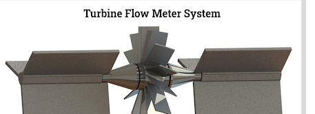
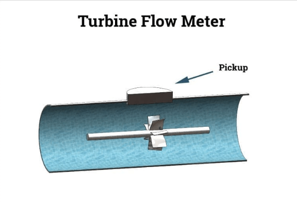
A turbine flow meter uses a rotor with angled blades that rapidly rotate to measure the flow’s energy in either a clockwise or counterclockwise direction. The smooth rotation of the rotor is made possible by the blades being attached to a rod that has bearings. The blades that spin the rod rotate at a faster rate as the flow moves quickly. The blades have magnets, temperature, or pressure sensors attached to them to read the flow rate.
A small piece of metal close to the meter is passed by the blades as they turn. An accurate indication of the flow rate is provided by the amount of time it takes for the blades to pass the metal object. The operation of a turbine system is unaffected by the flow direction.
Types of Mass Flow Meters, Chapter 3
An open channel is open to the atmosphere, whereas a closed conduit is enclosed, and flow can be either an open channel or a closed conduit. The flow in an open channel is caused by gravity. Closed conduit flow is caused by the conduit’s pressure differences.
The various types of mass flow meters are numerous, complex, and evolve with their industrial applications. Coriolis, ultrasonic, thermal, turbine, differential, positive displacement, vortex, and gyroscopic will all be discussed in this discussion.
Types of Mass Flow Meters
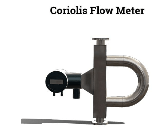
Flow Meter by Coriolis
The fluid flows through U-shaped tubes that vibrate in an angular harmonic oscillation with Coriolis mass flowmeters. A measurable phase shift in the tubes is brought on by the deformation of the tubes and the addition of an additional vibrational component to the oscillation. Coriolis flow meters can be used to measure a fluid’s density and are extremely accurate—better than 0.1 percent—with a turndown rate of more than 100:1.
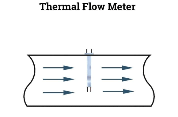
Thermal mass flow meters are popular because they can measure mass flow without moving parts, making them suitable for demanding applications like saturated gas and requiring less upkeep. Temperature and pressure correction devices are not required for the thermal mass flow meter to function properly. Thermal mass flow meters can be used with a wide variety of media and are extremely accurate regardless of their design.
Two heated sensors are located in the fluid flow path of thermal mass flow meters. One of the sensors produces heat from the flow stream in proportion to the mass flow rate. The mass flow rate is the difference in temperature between the sensors. Variations in the fluid’s temperature, pressure, heat capacity, and viscosity all play a role in determining a thermal mass flow meter’s accuracy.
Mass Flow Meters for Turbines
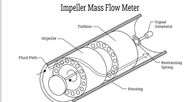
Impeller and twin turbine mass flow meters are two common types of turbine mass flow meters. The two distinct designs utilize similar processing techniques, including a turbine’s vanes being turned by fluid passing through a pipe. The pace of its twist estimates the stream rate with an exactness of 2% for gasses or steam and 1.5% for fluids. Turbine meters lack the precise accuracy of other flow meters because they use temperature and pressure sensors to measure velocity.
Impeller Turbine Mass Flow Meters: An impeller and a turbine, two rotating elements directly in the path of the fluid stream, have channels through which the fluid can pass in an impeller mass flow meter. Powered by a synchronous motor and a magnetic coupling, the impeller provides an angular velocity for the flow that passes through the meter.
The turbine, which is located downstream of the impeller, reduces the flow’s angular speed and generates torque proportional to the flow’s angular momentum. The turbine is held in place by a spring, which deflects at an angle proportional to the flow’s torque to produce the mass flow measurement.
The principle of fluid inertia underpins the operation of twin turbine mass flow meters. The turbines are connected to a flexible calibration torsion piece by being mounted on a single shaft. Over the turbines, a pick up is mounted, and magnets are inserted into the turbine assemblies.
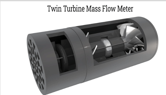
The flexible coupling directs the turbines’ movement, causing the assembly to rotate in unison. Between the turbines, which are the flow’s mass and angular momentum, there is an angular phase shift as they turn. The angular displacement between the turbines increases as the mass flow rate increases.
Gyroscopic Mass Flow Meter
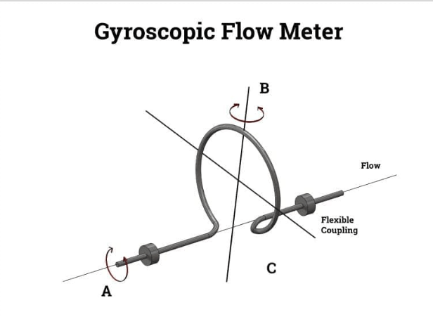
Similar to a Coriolis mass flow meter, a gyroscopic mass flow meter functions. It has a pipe in the shape of a C and a leaf spring in the shape of a T that acts like a tuning fork. The pipe experiences an acceleration similar to that of Coriolis when the tuning fork is stimulated by an electromagnetic field. The amount of deflection of the C-shaped pipe caused by the generated forces is proportional to the mass flow rate but inversely proportional to the pipe’s stiffness.
During the oscillation of the tuning fork, the pipe’s deflection is measured. The result from the redirection is a heartbeat width tweak that is relative to the mass stream
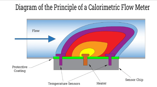
Calorimetric Flow Meters
Thermal flow meters that measure the asymmetrical temperature of a fluid flow are known as caloriemetric flow meters. The physical laws of heat are used by two heat sensors to measure the flow rate around a heating element.
The heating element’s temperature is measured by one of the sensors, which is continuously heated. The heat of the fluid in the pipe is measured by the second sensor. The temperature difference between the two sensors decreases with increasing flow rate. The idea of flowing media having a cooling effect is the foundation of the concept. The heat element absorbs heat as the cooling media moves past it. The cooling effect is greater the more media that passes through.
Flow Switch A flow switch uses a reed switch, paddle, or relay to communicate with the system’s controller to direct the flow. The information that is transmitted instructs the control system to either turn on or off. It’s a way to prevent damage and keep the system safe. A flow switch’s information makes it easier to control the flow rate. A paddle that is connected to the flow switch will move as the flow moves by, activating the switch.
Digital Flow Meter In contrast to other kinds of flow meters, which use mechanical methods to get a flow rate, a digital flow meter shows the flow rate precisely and accurately without using any kind of mechanism. Ultrasonic flow meters and magnetic flow meters are two common data collection methods for digital flow meters. Digital flow meters are sophisticated enough to be able to interface with other electronic devices and interpret data in a variety of ways.
Air Flow Meter Depending on the design, air flow meters offer multiple readings, such as the air’s mass, volume, and flow rate. Even though they are called “air flow meters,” they can also measure other gases like hydrogen, helium, and nitrogen. Hot wire, vane, cup anemometer, and pitot are the four types of air flow meters. The method of determining air flow is different for each type.
Fuel Flow Meter Fuel accounts for 50% to 70% of the operating costs of a shipping and transport system, making it a significant expense. As a result, fuel flow meters and their precise readings have become essential for fuel transfer.
To measure mass flow rate, fuel flow meters use the Coriolis effect, which eliminates the need for mathematical calculations. It does not depend on the fuel’s density, pressure, or viscosity because it uses the thermodynamic heat conduction principle.
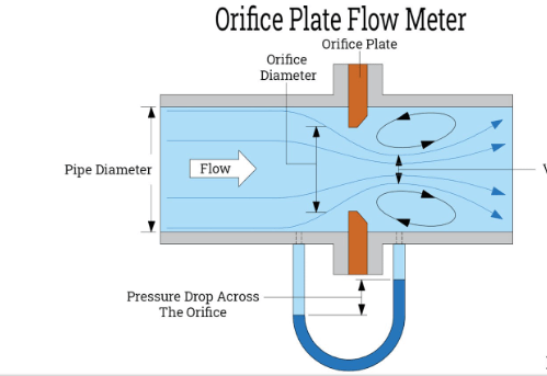
Orifice Plate Flow Meter An orifice plate flow meter is a kind of differential pressure flow meter that is used for heavy-duty applications because it is durable and cheap. An orifice plate that reduces, restricts, and generates differential pressure is used to measure the flow. It is fitted between pipe spines and works on the rule that tension and speed of a liquid are connected. The pressure falls as the velocity rises. The pressure rises when the velocity decreases.
Water Flow Meters There are paddle wheel, positive displacement, magnetic, and ultrasonic water flow meters to choose from. The open or closed channel water flow that is being measured determines the kind of water flow meter to use. From the source to the point where the water is distributed, water flow meters are strategically positioned throughout a water flow system.
Depending on the system’s sophistication and design, the flow rate is recorded on an electronic or mechanical device in cubic meters or liters.
Peak flow meters are a type of medical instrument that measure the efficiency with which the lungs expel air. The peak flow meter’s mouthpiece measures the force of the air in liters per minute and provides a numerical reading when the patient blows air through it.
A peak flow meter is used to determine whether the airway is narrow enough to be a serious symptom and how narrow it is. Peak flow meters provide a reference for further diagnosis and can be used to measure daily breathing habits.
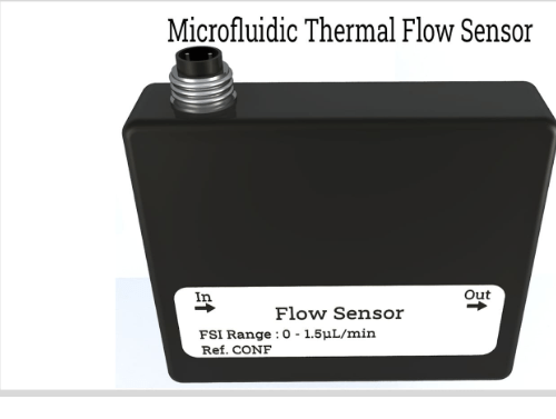
Microfluidic Thermal Flow Meter (MFS) For ultra-flow rate monitoring, microfluidic thermal flow sensors are highly accurate liquid mass flow sensors. They must be connected to a specialized sensor reader and operate digitally. Up to femtoliters (fL), which is one quadrillionth of a liter, fluids can be handled in microfluidics. At that level, fluids behave differently from normal fluids.
The advantages of MFS gadgets incorporate their capacity to investigate less volume of tests. Due to their compact design, multiple operations can be carried out simultaneously and provide excellent data.
Chapter Four – Mass Flow Meter Types of Readings
Mass or volumetric measurements of mass flow are used to measure the number of molecules in a gas, while volumetric measurements are used to measure the distance between molecules. Temperature and pressure have an effect on measurements.
The actual flow rate, or volumetric flow rate, is the three-dimensional space occupied by a gas as it moves through the instrument at the pressure and temperature that have been measured.
The volumetric flow rate, which is the amount of space that molecules occupy when measured at a standard temperature and pressure, is the number of molecules that flow through a mass flow meter.
Mass flow meters use a variety of measurements to provide data. They are based on the force that is generated by the flowing stream when it strikes an obstruction in the stream, which can also be used to measure velocity.
The density is measured in liters or kilograms per second, which are the units of measurement for gas and liquid flow. In contrast to gasses, which are influenced by pressure and temperature, liquids have a density that is independent of the conditions in their immediate environment.
The flow rate of liquids or gases is measured in gigajoules per hour (BTUs per day) when they are pumped for energy use. The energy flow rate is determined by a flow computer by utilizing the mass and volumetric flow rates.
Because their volume changes when heated, cooled, or put under pressure, gases are difficult to measure. A mass flow meter’s gas flow rate can be read in either actual or standard units, such as acm/h, which stands for actual cubic meters per hour, sm3/sec, kscm/h, or MMSCFD, which stands for million standard cubic feet per day.
Thermal, Coriolis, or controller meters are the most effective for determining gas flow rate.
Coriolis Flow Meter Thermal Flow Meter The units used to measure liquids can be gallons per minute, liters per second, bushels per minute, or cubic meters per second, depending on the application and industry.
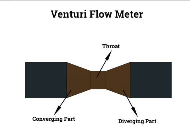
Venturi Effect
When a fluid flows through a narrow space, the pressure drops due to the venturi effect. The speed of the liquid builds, while its strain diminishes. The pressure decrease cancels out the pressure increase.
Using Bernoulli’s equation, which states that the velocity of a liquid increases in proportion to a decrease in pressure, the Venturi effect measures the velocity of a fluid in a pipe. Using the formula Q (liquid flow rate) = A (pipe area in square meters) multiplied by v (liquid velocity in meters per second), the flow rate is expressed in gallons per minute, liters per second, or cubic meters per second.
Accuracy of a Flow Meter The accuracy and amount of error in a flow meter are two indicators of its performance. A flow meter’s accuracy is expressed as a percentage of:
Calculations should be expressed in percentages of the actual rate, which can be minimum, normal, or maximum, when discussing flow rate accuracy. Full Scale – %FS Calibrated Span – %CS Upper Range Limit – %URL The selection of the appropriate mass flow meter for an operation can be aided by these findings.
Concerns About the Accuracy of Flow Meters in Chapter 5 The flow of liquids and gases necessitates constant, vigilant monitoring with precise measurements and readings. A decrease in efficiency and the possibility of equipment damage result from errors in readings, calculations, and adjustments. Understanding the reasons for the issues with meter readings can forestall expected fixes and stoppage of creation. The following are a few instances of conditions that can cause hardships with mass stream meter readings or harm to the meter.
Slurry:
Slurry can be either settling or non-settling and contains microscopic particles of less than 60 to 100 microns. The slurry’s particles can coagulate and clog the line or be abrasive enough to damage a flow meter.
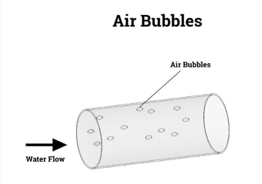
Air Spheres:
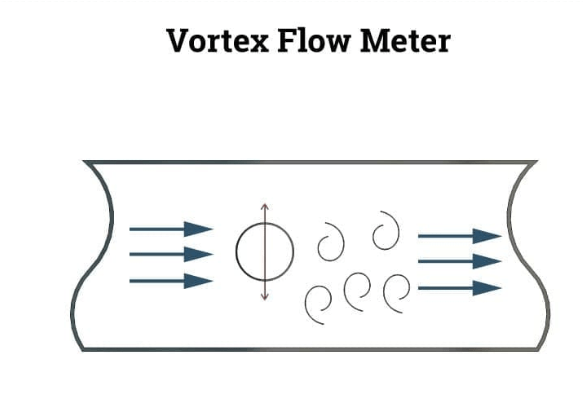
Impurities and air can combine with a fluid in open systems that are exposed to the air to form bubbles. Air bubbles prevent the formation of vortices in vortex flow meters. They prevent ultrasonic waves from causing malfunctions and inaccurate readings in ultrasonic flow meters.
Deviations in the Flow:
At the point when a liquid is moving through a straight line, stream speed is uniform and stable. The flow velocity changes and becomes irregular as a result of bends or angles in a pipe, drifting away from the center of the pipe or swirling. The degree of irregularity will determine the amount of measurement error
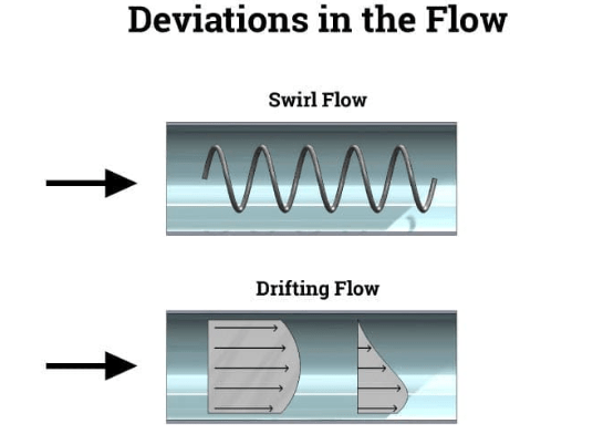
.
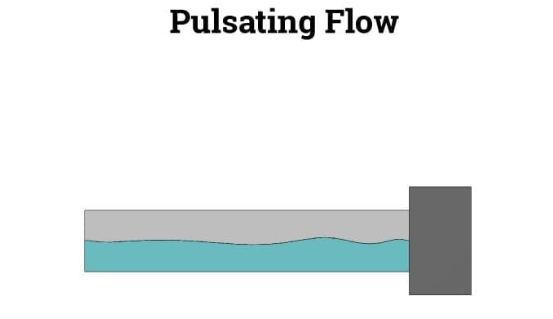
Pulsating Flow:
The fluid flow can accelerate or decelerate beyond the range of the mass flow meter, resulting in pulsations. The actual flow rate will be greater than the reading on the meter. This issue is known to be caused by reciprocating pumps. A damper, like an accumulator, can reduce pulsations. Expanding the stream meter’s season of reaction is another action.
Pipe Vibration:
The operation of machinery close to the pipe or the opening and closing of valves are two examples of the many different ways that pipes can be made to vibrate. Vibrations can occur when a fluid enters a pipe in some circumstances. In those circumstances, vortex and coriolis meters will not provide accurate measurements. Ultrasonic flow meters, on the other hand, are unaffected by vibrations and therefore cannot measure.
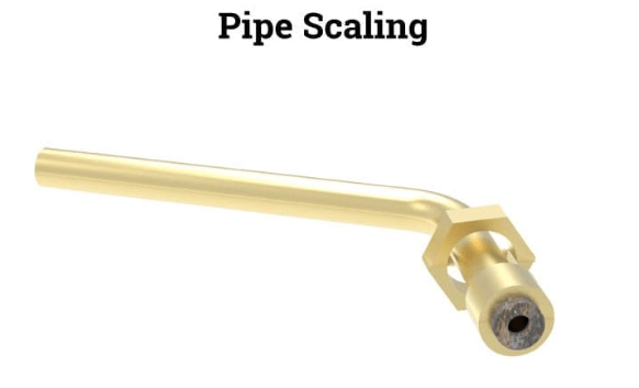
Scaling:
Scaling occurs when groundwater’s tiny metal particles crystallize and stick to pipes’ walls. The flow path narrows as scaling increases, preventing liquid flow. The flow meter can also be connected to scaling. Scaling will result in reading errors for flow meters with paddle wheels or floating elements.
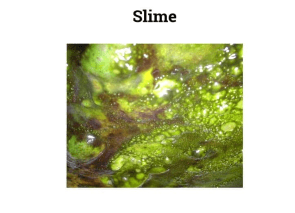
Slime:
Slime is made from microorganisms, algae, and other living things that can be sticky or muddy. Slime, like scaling, rust, sludge, and slurry, can clog a mass flow meter and prevent fluids from flowing through it. Because it conducts electricity, slime can also lead to erroneous readings.
Calorimetric Measuring Principle
The calorimetric principle makes it possible to measure media pressure and flow velocity. The flow rate can be determined regardless of the media’s electrical conductivity, viscosity, or density using two sensors that monitor the transformation of heat.
The estimating system relies upon the cooling of a warmed sensor by the media. The sensor’s cooling rate is directly related to the mass of the media. The media’s body with the highest temperature must give off heat as energy. The mass flow rate, which is the measurement of changes in a body’s state variables to calculate heat transfer, and the temperature difference determine the amount of heat released.
Conclusion
Mass stream meters measure the volume or mass of a gas or fluid going through a framework at a decent point.
Depending on the industry and the application, mass flow meters are referred to by different names and measure mass and volumetric flow rates.
Open channel liquid flow is open to the atmosphere, whereas closed conduit liquid flow is enclosed. Both types of liquid flow exist.
Liquid and gas flow necessitates constant, vigilant monitoring using precise measurements and readings.
Mass or volumetric measurements of mass flow are used to measure the number of molecules in a gas, while volumetric measurements are used to measure the distance between molecules.