


Alternating current (AC) is transformed into direct current (DC) with the help of a rectifier circuit. Half-wave, full-wave, and bridge rectifiers are the most common types of rectifiers. All of these rectifiers serve the same primary purpose—converting current—but they do not effectively convert AC to DC current. Both the bridge rectifier and the center-tapped full wave rectifier convert effectively. Electronic power supplies typically include a bridge rectifier circuit in their components. Numerous electronic circuits require a redressed DC power supply for fueling the different electronic fundamental parts from accessible AC mains supply. This rectifier can be found in a wide range of electronic AC power devices, including motor controllers, modulation processes, welding applications, and home appliances. An overview of the operation of a bridge rectifier is presented in this article.
How does a bridge rectifier work?
Alternating Current (AC) to Direct Current (DC) Converters that convert mains AC input to DC output are known as bridge rectifiers. Power supplies that provide the necessary DC voltage for electronic devices or components frequently make use of bridge rectifiers. They can be made with any combination of controlled solid-state switches and four or more diodes.
A suitable bridge rectifier is chosen based on the load current requirements. When selecting a rectifier power supply for an appropriate electronic circuit’s application, ratings and specifications of components, breakdown voltage, temperature ranges, transient current rating, forward current rating, mounting requirements, and other factors are taken into consideration.
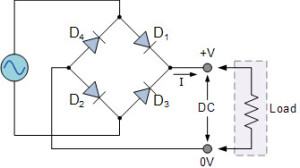
Construction The construction of the bridge rectifier is depicted below. A load resistor (RL) and four diodes, D1, D2, D3, and D4, can be used to create this circuit. To efficiently convert AC (alternating current) to DC (direct current), these diodes can be connected in a closed-loop pattern. The absence of an exclusive center-tapped transformer is the design’s main advantage. Thus, the size, as well as cost, will be diminished.
The o/p DC signal can be achieved across the RL once the input signal is applied to the two terminals A and B. The load resistor in this case is connected between two terminals, such as C and D. Two diodes can be arranged in such a way that electricity flows through both of them every half cycle. During the positive half cycle, the pairs of diodes like D1 and D3 will conduct electric current. Similarly, during a negative half cycle, the D2 and D4 diodes will carry electric current.
Diagram of a Bridge Rectifier The bridge rectifier has the advantage of producing almost twice as much voltage as a full-wave rectifier with a center-tapped transformer. However, this circuit resembles a low-cost rectifier because it does not require a center-tapped transformer.
PCBWay The bridge rectifier circuit diagram includes a transformer, diode bridge, filtering, and regulators in various stages. A regulated DC power supply, which powers a variety of electronic devices, typically consists of all of these blocks.
A step-down transformer that alters the amplitude of the input voltage serves as the circuit’s first stage. To step down the AC mains supply from 230V to 12V, the majority of electronic projects use a 230/12V transformer.
Diagram of a Bridge Rectifier The next stage is a diode-bridge rectifier, which, depending on the kind of bridge rectifier, uses four or more diodes. Considerations such as the device’s Peak Inverse Voltage (PIV), forward current If, voltage ratings, and other parameters must be taken into account when selecting a particular diode or other switching device for a rectifier that matches it. It is responsible for conducting a set of diodes each half cycle of the input signal to generate unidirectional or DC current at the load.
Filtering is required to produce a pure DC because the output from the diode bridge rectifiers is pulsating. Separating is typically performed with at least one capacitors connected across the heap, as you can see in the beneath figure wherein smoothing of the wave is performed. The output voltage also affects this capacitor’s rating.
A voltage regulator that keeps the output voltage constant is the final stage of this regulated DC supply. If the microcontroller operates at 5V DC, but the output after the bridge rectifier is around 16V, a voltage regulator is required to reduce this voltage and maintain a constant level regardless of input voltage changes.
Operation of a Bridge Rectifier A single-phase bridge rectifier, as previously mentioned, consists of four diodes that are connected across the load. We must consider the following circuit for demonstration purposes in order to comprehend the bridge rectifier’s working principle.
D1 and D2 of the input AC waveform diodes exhibit forward bias while D3 and D4 exhibit reverse bias during the Positive half cycle. The load current begins to flow through the diodes D1 and D2 when the voltage rises above their threshold levels, as depicted by the red line in the diagram below.
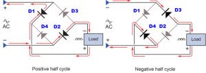
The diodes D3 and D4 are biased forward during the negative half cycle of the input AC waveform, while the diodes D1 and D2 are biased in the opposite direction. When the D3 and D4 diodes begin to conduct, as depicted in the figure, load current begins to flow through them.
We can see that the direction of the load current is the same in both cases—up to down, as depicted in the figure—so it is unidirectional, or DC current. As a result, the input AC current is transformed into a DC current using a bridge rectifier. This bridge wave rectifier produces a pulsating output at the load; however, in order to produce pure DC, an additional filter such as a capacitor is required. Different bridge rectifiers perform the same operation, but controlled rectifiers require thyristor triggering to drive the load current.
Bridge Rectifier Types
Based on these factors, bride rectifiers are divided into several categories: type of supply, capability of controlling, bride circuit configurations, and other factors The most common types of bridge rectifiers are single-phase and three-phase rectifiers. Both these sorts are additionally ordered into uncontrolled, half controlled, and full controlled rectifiers. The following is a brief description of a few of these rectifiers.
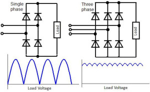
Rectifiers with One Phase or Three Phases These rectifiers are determined by the type of supply—a supply with one phase or three phases. For converting AC into DC, a single phase bridge rectifier uses four diodes, whereas a three-phase rectifier uses six, as depicted in the figure. Depending on the circuit components, such as diodes, thyristors, and so forth, these can be either uncontrolled or controlled rectifiers once more
.
Bridge Rectifiers Without Control
As depicted in the figure, this bridge rectifier rectifies the input using diodes. because the diode is a one-way device that lets current flow only in one direction. The rectifier’s configuration of diodes prevents power from varying in response to load requirements. Therefore, constant or fixed power supplies employ this kind of rectifier.
Controlled Bridge Rectifier In this type of rectifier, also known as an AC/DC converter, controlled solid-state devices like SCRs, MOSFETs, IGBTs, and so on are used in place of uncontrolled diodes. are utilized to adjust the output power for varying voltages. The output power at the load is appropriately altered by activating these devices at various times.
Controlled Bridge Rectifier Controlled Bridge Rectifier Bridge Rectifier IC The pin configuration of a bridge rectifier, such as the RB-156 IC, is discussed further down.
Pin 1 (Line/Phase): Since this is an AC input pin, phase wire can be connected from the AC supply to this phase pin.
Pin 2 (Negative): The neutral wire from the AC supply can be connected to this neutral pin via the AC Input pin.
Positive pin three: This is the DC yield pin where the positive DC voltage of the rectifier is acquired from this positive pin
Pin-4 (Negative/Ground): Specifications The subcategories of this RB-15 Bridge rectifier range from RB15 to RB158. This is the DC output pin from which the rectifier gets its ground voltage. The RB156 is the most frequently utilized of these rectifiers. The following are some of the RB-156 bridge rectifier’s specifications.
The maximum peak reverse voltage is 800V, and the o/p DC current is 1.5A. The output voltage is: 2VRMS) – 2 Volts The RB-156 is the most commonly used compact, low-cost, and single phase bridge rectifier. It has a maximum input voltage of 560V, a voltage drop of 1V at 1A, and a surge current of 50A. Because it has the highest i/p AC voltage, 560V, this IC can be used in all countries for one-phase mains supply. The most elevated DC current of this rectifier is 1.5A. This IC is the most ideal decision in the undertakings for changing over AC-DC and give up to 1.5A.
Span Rectifier Attributes
The attributes of scaffold rectifier incorporate the accompanying
Swell Component
Top Reverse Voltage (PIV)
Productivity
Swell Variable
The estimation of the result DC sign’s perfection utilizing a variable is known as the wave factor. In this case, the o/p DC signal can be a smooth DC signal with few ripples, while the o/p DC signal can be a high pulsating DC signal with many ripples. It can be expressed mathematically as the ratio of the ripple voltage to the pure DC voltage.
PIV (Peak Inverse Voltage) The peak inverse voltage, or PIV, is the highest voltage value that is coming from the diode when it is connected in reverse bias condition throughout the negative half cycle. The ripple factor for a bridge rectifier can be expressed as = (Vrms2/VDC) 1. The ripple factor value of the bridge rectifier is 0.48. There are four diodes in the bridge circuit, D1, D2, D3, and D4.
In the positive half cycle, the two diodes like D1 and D3 are in the leading position though both the D2 and D4 diodes are in the non-directing position. The diodes D1 and D3 are in the non-conducting position during the negative half cycle, whereas D2 and D4 are in the conducting position during the positive half cycle.
Efficiency The rectifier’s ability to convert AC (Alternating Current) into DC (Direct Current) is primarily determined by its efficiency. The efficiency of the rectifier can be described as It is the AC i/p power to DC o/p power ratio. The maximum efficiency of the bridge rectifier is 81.2%.
η = DC o/p Power/AC I/p Power
Span Rectifier Waveform
From the scaffold rectifier circuit graph, we can presume that the progression of current across the heap resistor is equivalent all through the positive and the negative half cycles. The o/p DC signal’s polarity can be completely positive or negative. It’s 100% positive in this instance. A negative DC voltage can be achieved by turning the diode in the opposite direction.
As a result, this rectifier makes it possible for current to flow throughout the i/p AC signal’s positive and negative cycles. The output waveforms of the bridge rectifier are depicted below.
Why is it referred to as a bridge rectifier?
This is the rectifier circuit that performs the best when compared to other types of rectifiers. As the name suggests, this type of full-wave rectifier makes use of four diodes connected in a bridge configuration. A bridge rectifier is the name given to this kind of rectifier.
Why are four diodes used in the Bridge Rectifier?
The circuit of the bridge rectifier is constructed with four diodes to enable full-wave rectification without the use of a center-tapped transformer. In the majority of applications, this rectifier is mostly used to provide full-wave rectification.
In order to convert AC to DC effectively, a closed-loop arrangement of four diodes can be used. The absence of the center-tapped transformer, which reduces size and costs, is the arrangement’s primary advantage.
The following are some of the advantages of a bridge rectifier:
A full-wave rectifier has twice the rectification efficiency of a half-wave rectifier.
the higher Transformer Utilization Factor, output voltage, and power in the case of a full-wave rectifier.
The wave voltage is low and of higher recurrence, in the event of full-wave rectifier so basic sifting circuit is required
No middle tap is expected in the transformer optional so on account of a scaffold rectifier, the transformer required is less difficult. Even the transformer can be eliminated if voltage stepping up or down is not required.
Due to the fact that the current flows throughout the entire ac cycle in both the primary and secondary windings of the supply transformer, a power transformer of a smaller size can be utilized in the case of the bridge rectifier for a particular power output.
The efficiency of the rectifier is double that of a half-wave rectifier. It uses straightforward filter circuits for high frequency and low ripple voltage. The TUF is higher than that of a center-tapped rectifier. There is no need for a center tap transformer.
Four diodes are required.
The utilization of two additional diodes results in a decrease in the output voltage due to an additional voltage drop.
Since this rectifier requires four diodes, its price will be high.
Because the connection of the two diodes can be carried out in series and results in a double voltage drop due to the internal resistance of the diodes, the circuit is not suitable for use when only a small voltage needs to be rectified.
These circuits are very complicated. The bridge rectifier loses more power than the center-tapped rectifier.
An Application: Many electronic applications frequently require a Bridge Rectifier Regulated DC Power supply to convert AC power to DC. Converting the available AC mains power supply into a DC supply is one of the most straightforward and dependable methods. This transformation of the air conditioner sign to DC signal is finished utilizing a rectifier, which is an arrangement of diodes. Either a full-wave rectifier that rectifies both cycles of the AC signal or a half-wave rectifier that only rectifies one half of the signal can be used. The full-wave rectifier can be a middle tapped rectifier comprising of two diodes or an extension rectifier comprising of 4 diodes.
The bridge rectifier is shown here. The arrangement consists of four diodes arranged in such a way that the output receives a positive supply from the cathodes of two adjacent diodes and a negative supply from the anodes of the other two adjacent diodes. The negative of the AC supply is connected to the anode and cathode of the other two adjacent diodes, while the positive of the AC supply is connected to the anode and cathode of the other two adjacent diodes. As a result, four diodes are arranged in a bridge so that two alternate diodes conduct during each half-cycle, resulting in a DC voltage that repels.
The arrangement of the bridge rectifier in the given circuit delivers an unregulated DC output to an electrolyte capacitor through a current-limiting resistor. A voltmeter is used to check the voltage across the capacitor, which keeps going up as the capacitor charges until the voltage limit is reached. The capacitor discharges when a load is connected across it to supply the load with the required input current. A lamp acts as a load in this instance.
The following are the components that make up a regulated DC power supply:
a transformer that reduces the voltage of AC from high to low.
a bridge rectifier that changes the static AC into dynamic DC.
a capacitor-based filter circuit that eliminates AC ripples.
The step-down transformer transforms the 230V AC mains supply into 12V AC using an IC 7805 regulator. The bridge rectifier arrangement receives 12V AC, which causes the alternate diodes to conduct for each half cycle, resulting in a pulsating DC voltage with AC ripples. As a high pass filter, a capacitor connected across the output lets the AC signal pass through and blocks the DC signal. As a result, the DC signal that flows across the capacitor is unregulated and unfiltered. Relays, motors, and other electrical components can all be driven by this output. The output of the filter is connected to an IC 7805 regulator. It provides a constant, regulated 5V output that can be used as input to numerous electronic circuits and devices, including microcontrollers and transistors. Through a resistor, the 5V is used to bias an LED in this case.
This is all about the types, circuits, and working principles of the bridge rectifier theory. We hope that students will be able to build electronics or electrical projects and observe various electronic appliances with the help of this informative material on this topic. We are grateful for your focused attention to this article. Therefore, if you require any additional technical guidance or assistance selecting the appropriate component ratings for this bridge rectifier for your application, please write to us.
We hope you now understand the bridge rectifier’s concept and its applications. If you have any questions about this topic or the electrical and electronic project concept, please leave them in the comments section below
Controlled Bridge Rectifier by eng.cam Controlled Bridge Rectifier by engineersgarage Bridge Rectifier Operation by eniquest Bridge Rectifier Circuit and the output waveform by neilorme Bridge Rectifier by numato Uncontrolled Bridge Rectifiers by electronics-tutorials